Belt force measuring device

a technology of force measurement and belt, which is applied in the direction of instruments, pedestrian/occupant safety arrangements, force/torque/work measurement apparatus, etc., can solve the problem of a large number of individual components which can be connected to one another only at a relatively high cost, and achieves cost-effectiveness, good measurement results, and easy production

Inactive Publication Date: 2011-07-12
CONTINENTAL AUTOMOTIVE GMBH
View PDF11 Cites 3 Cited by
  • Summary
  • Abstract
  • Description
  • Claims
  • Application Information

AI Technical Summary

Benefits of technology

[0015]In one refinement, the first connection element has a lug. The lug serves to connect the connection element to a belt lock, a belt section or the vehicle body. Connections of this type can also be easily produced when the second connection element has a lug.
[0016]In one embodiment, a guide is formed on the stamped sheet metal part by a next fold, said guide allowing the connection elements to move one beneath the other in a guided manner. The guide permits very exact movement of the sensor element relative to the transmitter, and this leads to very good measurement results for the belt force.
[0017]It is very advantageous when the stamped sheet metal part is in the form of a leadframe on which the sensor element and / or evaluation electronics are / is arranged. As a result, separate cabling of the sensor element and the evaluation electronics is not required. The leadframe is fitted with the sensor element and the evaluation electronics and can likewise be used to conduct signals and current.
[0018]Furthermore, it is very advantageous when the stamped sheet metal part with the sensor element which is arranged on it, the transmitter and / or the evaluation electronics are / is encapsulated by a thermoplastic in order to protect against external influences. Thermoplastics can be processed in a very cost-effective manner and they provide high-quality and long-term protection against external influences such as dirt, moisture and mechanical loads.

Problems solved by technology

Belt force measuring devices of this type have the disadvantage that they comprise a large number of individual components which can be connected to one another only at a relatively high cost.

Method used


Image

  • Belt force measuring device
  • Belt force measuring device
  • Belt force measuring device

Examples


Embodiment Construction

[0027]Elements with an identical structure and function are provided with the same reference symbols throughout the figures.

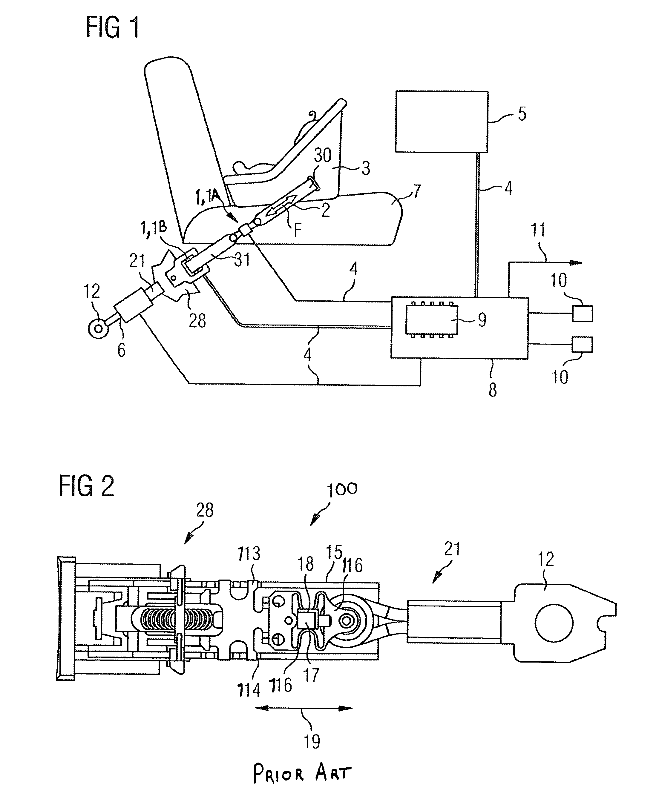
[0028]FIG. 1 shows a vehicle seat 7 with a safety belt 2, called belt 2 for short in the text which follows, as is usually used in passenger cars but also in heavy goods vehicles and buses. Furthermore, vehicle seats 7 of this type can also be found in rail-bound vehicles, aircraft and high-speed watercraft. The belt force measuring device 1 arranged at location 1A or 1B according to the invention can be used in all of these vehicles. FIG. 1 shows a child seat 3 on the vehicle seat 7, said child seat being secured by the belt 2. Instead of the child seat 3, it is of course also feasible for a grown person to be secured on the seat 7 by the belt 2. In the event of a traffic accident, considerable accelerations which have to be captured by the belt 2 are produced, with the belt 2 having to absorb up to 20 KN under full load. In order to protect the vehicle occupa...


PUM

PropertyMeasurementUnit
belt force measuringaaaaaaaaaa
force measuringaaaaaaaaaa
forceaaaaaaaaaa

Abstract

A belt force measuring device with a measuring spring, the displacement thereof being a measurement for the belt force, and with a transmitter, being assigned to the measuring spring, and with a sensor element, being also assigned to the measuring spring, wherein the displacement of measuring spring, effects a change of position of the sensor element in relation to the transmitter. The change of position is detected by the sensor element as measurement for the belt force and the belt force measuring device further has a first connecting element, connecting the measuring spring with a belt lock or a first belt section and a second connecting element, connecting the measuring spring, with a motor vehicle body or with a component of the motor vehicle body or a second belt section. To provide a belt force measuring device, being produced simply and cost effectively, the measuring spring, the first connecting element and the second connecting element are designated as a single-piece component.

Description

PRIORITY CLAIM[0001]This is a U.S. national stage of application No. PCT / EP2007 / 058538, filed on 16 Aug. 2007. which claims Priority to the German Application No.: 10 2006 038 594.2, filed, 17 Aug. 2006; the content of both being incorporated here by reference.BACKGROUND OF THE INVENTION[0002]1. Field of the Invention[0003]The invention relates to a belt force measuring device having a measuring spring whose deflection is a measure of the belt force, and having a transmitter which is associated with the measuring spring, and having a sensor element which is likewise associated with the measuring spring, with the deflection of the measuring spring effecting a change in the position of the sensor element relative to the transmitter, said change being detected by the sensor element as a measure of the belt force, and with the belt force measuring device also having a first connection element, which connects the measuring spring to at least one of a belt lock or a first belt section, an...

Claims


Application Information

Patent Timeline
Patent Type & Authority Patents(United States)
IPC IPC(8): G01L1/04
CPCB60R21/0155B60R22/30
Inventor SKARPIL, HARRY
Owner CONTINENTAL AUTOMOTIVE GMBH
Why Eureka
Try Eureka