Three dimensional electrical impedance tomographic method

Active Publication Date: 2016-11-24
NATIONAL CHIAO TUNG UNIVERSITY
View PDF8 Cites 10 Cited by
  • Summary
  • Abstract
  • Description
  • Claims
  • Application Information

AI Technical Summary

Benefits of technology

[0009]Another objective of the present invention is to provide a three dimensional electrical impedance tomographic method, which executes the systematization at the beginning of the measurement to produce vertical and horizontal images, then transmits and detects the horizontal and vertical detection signals. The received signals a

Problems solved by technology

However, the disadvantage of the EIT is that the resolution of the images produced are relatively low (when compare with CT or MRI) because it is limited by the number of electrodes which acquire the measurement data.
On the other hand, having too many numbers of electrodes could reduce the signal to noise ratio o

Method used


Image

  • Three dimensional electrical impedance tomographic method
  • Three dimensional electrical impedance tomographic method
  • Three dimensional electrical impedance tomographic method

Examples


third embodiment

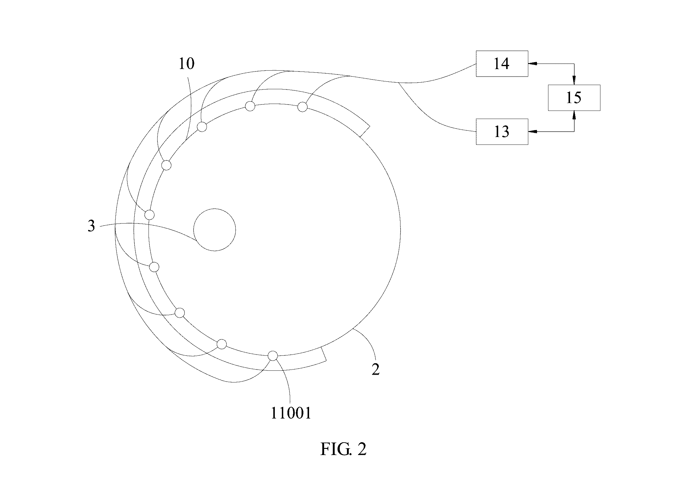
[0050]Please refer to FIG. 3A, FIG. 3B and FIG. 3C, which are a schematic diagram of the horizontal plane, a schematic diagram of the vertical plane and a schematic diagram of using the horizontal and vertical planes at the same time respectively according to the three dimensional electrical impedance tomographic method of the present invention, and takes the inward-looking as an example. The top view thereof is as same as FIG. 2.

[0051]In FIG. 3A, the plurality of electrodes 11001 located at the same horizontal plane 100 in the electrode array 11 are defined as a horizontal electrode set 111 and then a plurality of electrodes 11001 are selected from the horizontal electrode set 111 to be horizontal driving electrodes 1111. Next, a small amount of alternating current I is inputted from one of the plurality of horizontal driving electrodes 1111, and the other two horizontal driving electrodes 1111 output the alternating current αI and (1−α)I respectively. Other electrodes which are no...

fourth embodiment

[0079]Please refer to FIG. 8, which is a flowchart according to the three dimensional electrical impedance tomographic method of the present invention. According to another objective of the present invention, a three dimensional electrical impedance tomographic method is again provided, which includes the following steps:

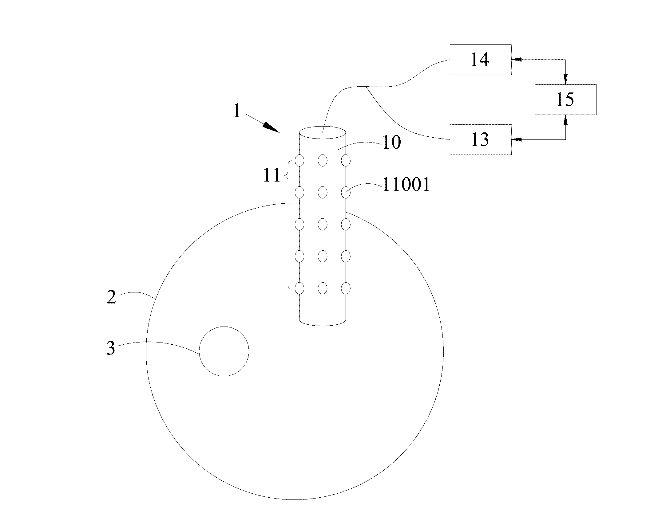
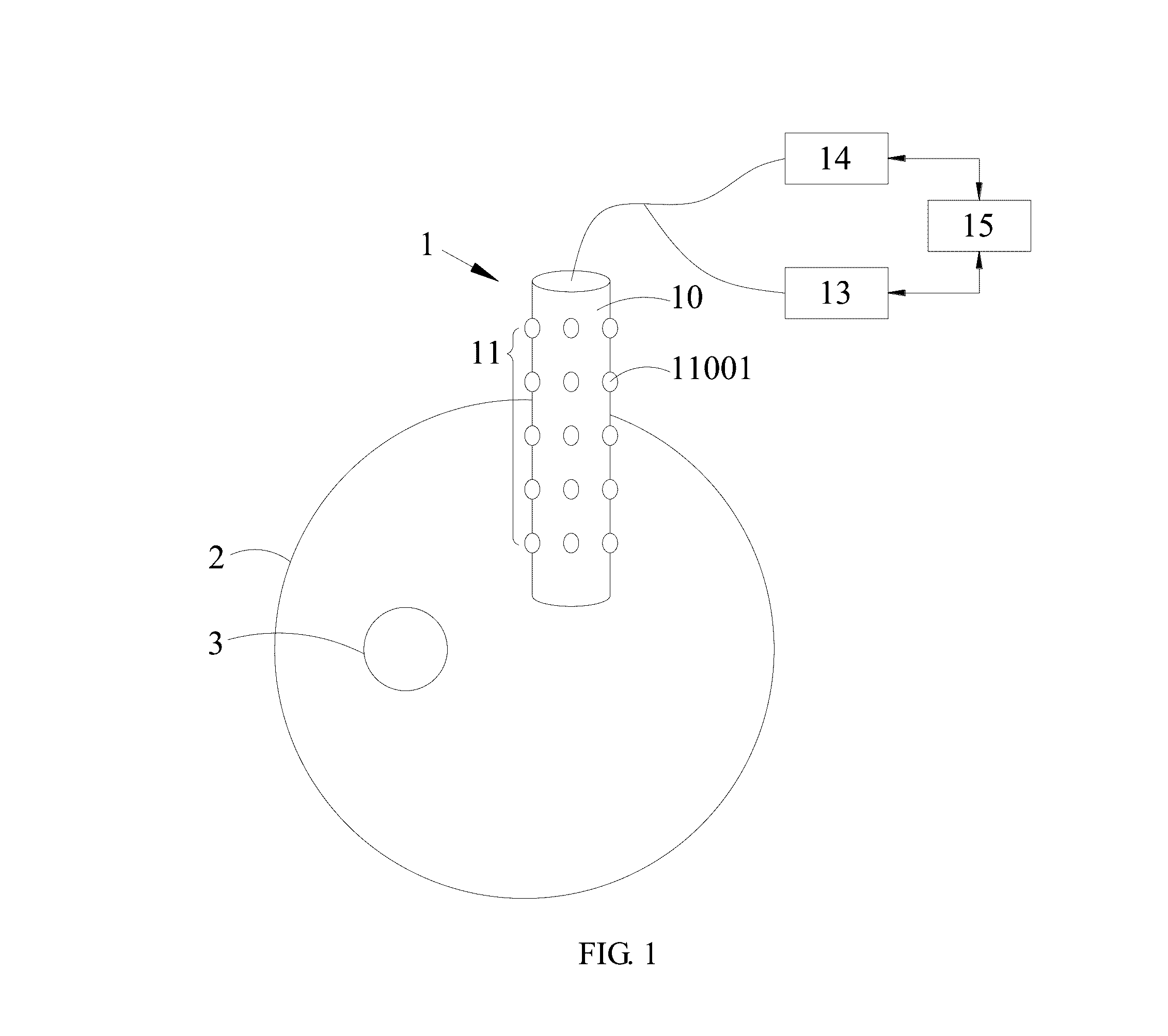
[0080]in step S21, an implantation body is disposed in an object to be imaged and the implantation body has a bearing surface. The shape of the bearing surface may be spherical, cylindrical, or irregular shaped object like a head or abdomen of a human body;

[0081]in step S22, an electrode array is disposed on the bearing surface. The electrode array has a plurality of electrodes;

[0082]in step S23, an electrode controller is disposed. The electrode controller is electrically connected to the plurality of electrodes respectively;

[0083]in step S24, the plurality of electrodes located at the same plane on the electrode array are defined as a plane electrode set. The elec...


PUM


Abstract

A three dimensional electrical impedance tomographic method is disclosed. The three dimensional electrical impedance tomographic method includes steps of disposing an implantation body, wherein an electrode array formed by a plurality of electrodes is disposed on the implantation body; disposing an electrode controller to control any electrode in the electrode array; generating more independent voltage data measured on the plurality of electrodes on the same curve surface by combining current control technology or virtual electrode technology; and performing a calculation to convert the plurality of horizontal or vertical voltage data into a three dimensional electrical impedance tomographic image.

Description

CROSS-REFERENCE TO RELATED APPLICATION[0001]This application claims priority from Taiwan Patent Application No. 104115807, filed on May 18, 2015, in the Taiwan Intellectual Property Office, the content of which are hereby incorporated by reference in their entirety for all purposes.BACKGROUND OF THE INVENTION[0002]1. Field of the Invention[0003]The present invention relates to an electrical impedance tomographic method, in particular to a three dimensional electrical impedance tomographic method.[0004]2. Description of the Related Art[0005]The electrical impedance tomography (EIT) is a medical imaging technology which produces tomographic images by measuring the conductivity distribution of a certain part of human body. It is currently applied to perform photography for the internal structure of biological organization. Compared to the other conventional imaging technologies such as positron emission tomography (PET), computed tomography (CT) and magnetic resonance imaging (MRI), th...

Claims


Application Information

Patent Timeline
IPC IPC(8): G01N27/02
CPCG01N27/02A61B5/0042A61B5/0536A61B5/0538A61B5/6814A61B2560/0468A61B2562/046
Inventor CHOI, CHARLES TAK MING
Owner NATIONAL CHIAO TUNG UNIVERSITY
Why Eureka
Try Eureka