Method for machining and estimating an optical lens designed as a smei-finished product

a technology of optical lenses and machining methods, applied in the direction of optical surface grinding machines, manufacturing tools, instruments, etc., can solve the problems of increasing manufacturing errors, entail greater complexity of individual prescription surfaces to be produced, etc., and achieve good measuring results, increase in precision, and rapid machining of the second side

Active Publication Date: 2010-07-01
SCHNEIDER GMBH & CO KG
View PDF3 Cites 7 Cited by
  • Summary
  • Abstract
  • Description
  • Claims
  • Application Information

AI Technical Summary

Benefits of technology

[0017]In connection with the design and arrangement according to the invention, it can be advantageous when the relative position between the first side and the block piece is incorporated into the estimation of the pre-specified form of the surface of the second side. The second side to be manufactured can be adjusted to the existing alignment of the first side relative to the block piece in order that the thinnest and thus lightest glass possible can be manufactured. Furthermore, the position of the second side can be selected in such a manner that a rapid machining of the second side is guaranteed with the lowest tool stroke possible.
[0018]It can furthermore be advantageous when the anticipated machine deviations are incorporated into the estimation of the pre-specified form of the second side. This procedure is generally dependent on the method according to the invention, namely the determination of the actual form of the surface of the second side. With the increase in precision according to the invention, the inclusion of the machine deviations, i.e. of the position protocol data, becomes more significant.
[0019]It can also be advantageous when a deflectometric measuring method, preferably a stereo measuring method such as that described in DE 10 2004 020 419 B3, is used. This method has already been known for over four years, and has in the past delivered very good measuring results. Furthermore, the influences originating from the surface of the second side which is to be machined on the measurement of the surface of the first side or the reflections which occur can be easily deducted from the estimation.
[0020]Furthermore, it can be advantageous when the pre-specified form of the surface of the second side of the lens is machined using milling by means of a milling cutter and / or a turning tool and / or ground and / or polished. The method according to the invention can equally well be used for machining lenses made of synthetic material, as for mineral lenses.

Problems solved by technology

The manufacture of individual prescription surfaces entails greater complexity of the surfaces to be produced.
Manufacturing errors become increasingly significant.

Method used


Image

  • Method for machining and estimating an optical lens designed as a smei-finished product
  • Method for machining and estimating an optical lens designed as a smei-finished product

Examples


Embodiment Construction

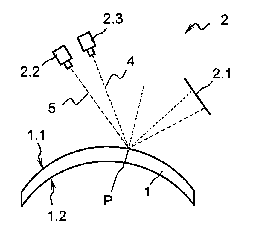
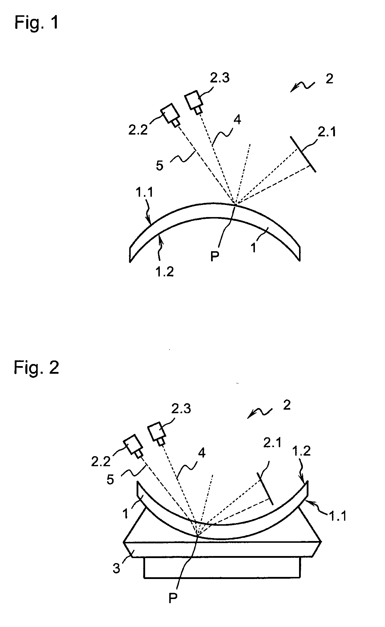
[0024]A lens 1 shown in FIG. 1 takes the form of a semi-finished product of a spectacle lens, and comprises a pre-finished first side 1.1. For the purpose of manufacturing a finished spectacle lens 1, an adjustment or machining of the second side 1.2 of the lens 1 is provided. When estimating a pre-specified form of the surface of the second lens 1.2, the real actual form of the surface of the first side 1.1 is measured using an optical measuring means 2. The optical measuring means 2 comprises a light source 2.1 for scattered light, by means of which scattered light is thrown in the form of defined patterns onto the surface of the first side 1.1 to be measured. The light reflects on the surface at a respective point P. The light reflected from this point P is recorded by a first camera 2.2 and a second camera 2.3 according to a respective light beam 4, 5. With the measuring method, the height and / or the surface standard of the surface of the first side 1.1 is determined, wherein th...


PUM

PropertyMeasurementUnit
optical measuringaaaaaaaaaa
optical propertyaaaaaaaaaa
material propertiesaaaaaaaaaa

Abstract

The invention relates to a method for machining and estimating an optical lens which is designed as a semi-finished product, with a pre-finished form of a first side and a second side to be machined, in which a pre-specified form of a surface of the second side to be machined is estimated, wherein prior to estimating the pre-specified form of the surface of the second side, an actual form of the surface of the first side is measured using measuring means and is incorporated into the estimation of the pre-specified form of the surface of the second side.

Description

FIELD OF THE INVENTION[0001]The invention relates to a method for machining and estimating an optical lens designed as a semi-finished product, with a pre-finished form of a first side and a second side which is to be machined, in which for the purpose of obtaining the desired optical property of the finished lens, a pre-specified form of a surface of the second side to be machined is estimated as a processing stage, wherein prior to the estimation of the pre-specified form of the surface of the second side, an actual form of the surface of the first side is measured using measurement means, or is measured by a measuring instrument, and the actual form of the surface of the first side is incorporated in the estimation of the pre-specified form of the surface of the second side.[0002]The first side or the second side can here be the front side or the rear side of the lens.BACKGROUND OF THE INVENTION[0003]A lens or spectacle lens generally has a front side and a rear side which are bo...

Claims


Application Information

Patent Timeline
Patent Type & Authority Applications(United States)
IPC IPC(8): G01B11/24B24B13/00
CPCB24B13/00B24B49/12
Inventor SCHNEIDER, GUNTERBUCHENAUER, HELWIGHUTTENHUIS, STEPHAN
Owner SCHNEIDER GMBH & CO KG
Why Eureka
Try Eureka