Method for measuring a current, and current-measuring device

a current and measurement device technology, applied in special purpose recording/indication devices, instruments, magnetic field offset compensation, etc., can solve the problems of limited measurement range of sensor arrangement, comparatively great offset error, and difficulty in adding analog or digital offset stabilization, etc., to achieve good measurement results, increase the accuracy, and extend the measurement range

Active Publication Date: 2021-10-19
SIEMENS AG
View PDF17 Cites 0 Cited by
  • Summary
  • Abstract
  • Description
  • Claims
  • Application Information

AI Technical Summary

Benefits of technology

[0011]Here, the sensors of the first type and of the second type in each case form two concentric annular arrangements of sensors with parallel orientation of the field-sensitive direction. If an individual sensor is overloaded, however, no switchover takes place in terms of sensors. In order to achieve good measurement results, a type-based switchover is carried out. The advantages of this method lie in an extension of the measurement range, a general increase in the accuracy and a possible reduction of the offset error.
[0012]The sensors of the first type are flux-gate field sensors and the sensors of the second type are Hall sensors. These sensors are available on the market at a reasonable cost. Moreover, the installation size thereof is accordingly small, meaning that they can be integrated into a measuring device in a simple manner.

Problems solved by technology

Owing to the “open loop” operation, the measurement range of the sensor arrangement is limited by the measurement range of the individual sensor.
Since the offset error of the individual sensors changes with the temperature and over time, an additional analog or digital offset stabilization is difficult.
In the previously known measurement setups, the comparatively great offset error and the low accuracy associated therewith is accepted at low currents.
It should be mentioned here that a simple direct compensation of the observed offset error is only possible with difficulty due to its non-deterministic time behavior and the significantly non-linear temperature behavior.
20 mT to an extent that the accuracy is considerably deteriorated.

Method used


Image

  • Method for measuring a current, and current-measuring device
  • Method for measuring a current, and current-measuring device

Examples


Embodiment Construction

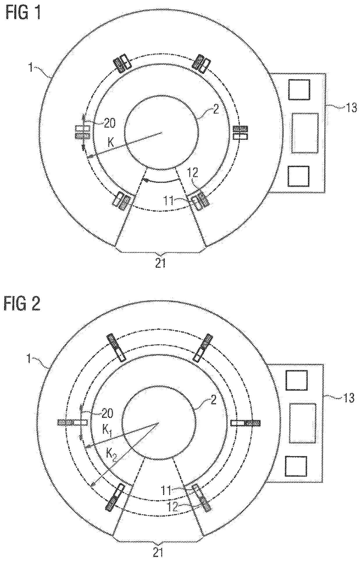
[0024]FIG. 1 shows a first exemplary embodiment of a current-measuring device 1 around an electrical conductor 2. Here, the current-measuring device 1 has a multiplicity of sensors 11 of a first type and, adjacent to this in each case, a plurality of sensors 12 of a second type. In this exemplary embodiment, adjacent means that the spacing between two sensors is smaller than the smallest extent of the sensors. The types differ, for example, in their measuring principles in this context. The sensors of different types are arranged on a common circular path K. In this context, the arrangement takes place such that the field orientation 20 which can be measured by the respective sensor is oriented tangentially to the circular path. In order to be able to evaluate the measurement signals of the individual sensors, the current-measuring device 1 has an evaluation electronics unit 13. In order to arrange the measuring device 1 around the electrical conductor in a simple manner, it has pro...


PUM


Abstract

In a method for measuring a current, a plurality of flux-gate field sensors is arranged with radial symmetry on a first circumferential path, and a plurality of Hall sensors is arranged with radial symmetry on a second circumferential path such that a one of the flux-gate field sensors is placed adjacent a one of the Hall sensors, with the flux-gate field sensors having a sensitivity which is higher by a factor 5 to 20 than a sensitivity of the Hall sensors. At least one of the plurality of flux-gate field sensors is evaluated so as to determine a current intensity, when two of the flux-gate field sensors generate measurement values within a measurement range, or at least one of the plurality of Hall sensors is evaluated so as to determine a current intensity, when the measurement values of the two flux-gate field sensors are outside of the measurement range.

Description

CROSS-REFERENCES TO RELATED APPLICATIONS[0001]This application is the U.S. National Stage of International Application No. PCT / EP2018 / 058588, filed Apr. 4, 2018, which designated the United States and has been published as International Publication No. WO 2018 / 185151 A1 and which claims the priority of European Patent Application, Serial No. 17165542.6, filed Apr. 7, 2017, pursuant to 35 U.S.C. 119(a)-(d).BACKGROUND OF THE INVENTION[0002]The invention relates to a method for measuring a current by means of a current-measuring device.[0003]Current-measuring devices, also referred to as current sensors, are used in order to measure or determine currents at specific points within electrical installations. In this context, a sensor arrangement for a current-measuring device and a corresponding evaluation method are considered, which enable an energy-efficient measurement of currents between 400 A and 10 kA without a flux concentrator (flux circuit). This sensor arrangement dispenses wit...

Claims


Application Information

Patent Timeline
Patent Type & Authority Patents(United States)
IPC IPC(8): G01R15/08G01R15/20G01R15/18
CPCG01R15/08G01R15/185G01R15/202G01R33/0005G01R33/0017G01D3/02
Inventor CHAHID, ABDERRAHIMHOFFMANN, INGOLFITZKE, ALEXANDERWEISS, ROLAND
Owner SIEMENS AG
Why Eureka
Try Eureka