Method and Device for Magnetic Field Correction for an NMR Machine

Inactive Publication Date: 2015-12-31
COMMISSARIAT A LENERGIE ATOMIQUE ET AUX ENERGIES ALTERNATIVES
2 Cites 0 Cited by

AI-Extracted Technical Summary

Problems solved by technology

For this purpose, specially configured magnets are designed that produce a field that is extremely homogeneous, but rarely sufficiently homogeneous to enable spectroscopy to be performed without additional adjustments.
This is particularly true when the sample itself often gives rise to distortions in the magnetic field because of...

Method used

[0082]The invention also makes it possible to make coils for correcting the gradients Gx, Gy, and Gz from the iso-contours of a flux function, e.g. as shown in FIGS. 8 to 10, which relate respectively to a coil for correcting the gradient Gx, to a coil for correcting the gradient Gy, and to a coil for correcting the gradient Gz. FIGS. 8 and 10 show respective masks 114A, 114B, and 114C for making conductive tracks on a face of a printed circuit so as to constitute winding elements for the gradients Gx, Gy, and Gz. These masks show in particular passages for passing current between the tracks correspondi...

Benefits of technology

[0040]It should be observed that emphasizing the terms along the axis at the magic angle, as in the preferred implementations of the invention, is particularly pertinent when the rotation of the sample in an experiment rotating at the magic angle (“magic angle spinning” or (MAS)) reaches speed...

Abstract

A device for magnetic field correction in an NMR system includes a device for creating a homogeneous main magnetic field along a direction Oz in a zone of interest ZI, a device for supporting a sample with a main dimension of the sample being oriented at an angle θ0 other than zero relative to the direction Oz, gradient coils, and radiofrequency coils. The device also includes a set of correction coils positioned around the device for supporting the sample. Each correction coil presents an axis coinciding with the direction Oz and includes winding elements made from iso-contours of a flux function that are regularly spaced apart between limits of the flux function on a cylinder.

Application Domain

Electric/magnetic detectionMeasurements using magnetic resonance +1

Technology Topic

Radio frequencyCondensed matter physics +1

Image

  • Method and Device for Magnetic Field Correction for an NMR Machine
  • Method and Device for Magnetic Field Correction for an NMR Machine
  • Method and Device for Magnetic Field Correction for an NMR Machine

Examples

  • Experimental program(1)

Example

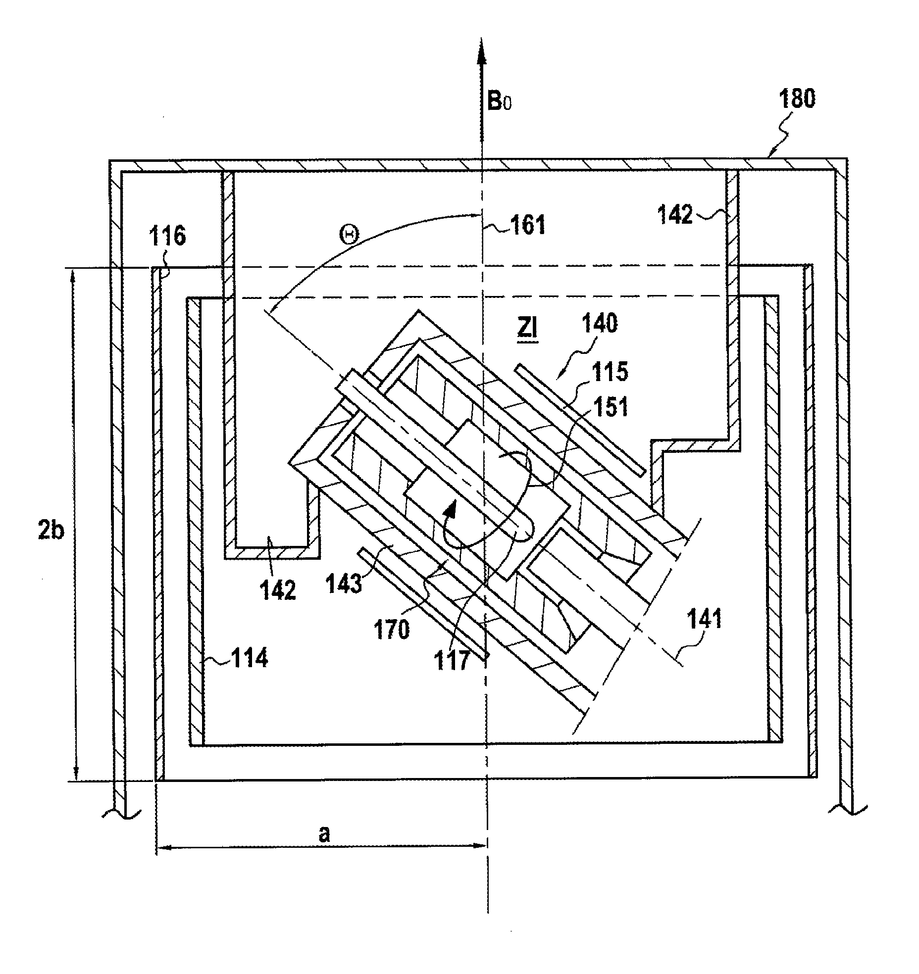
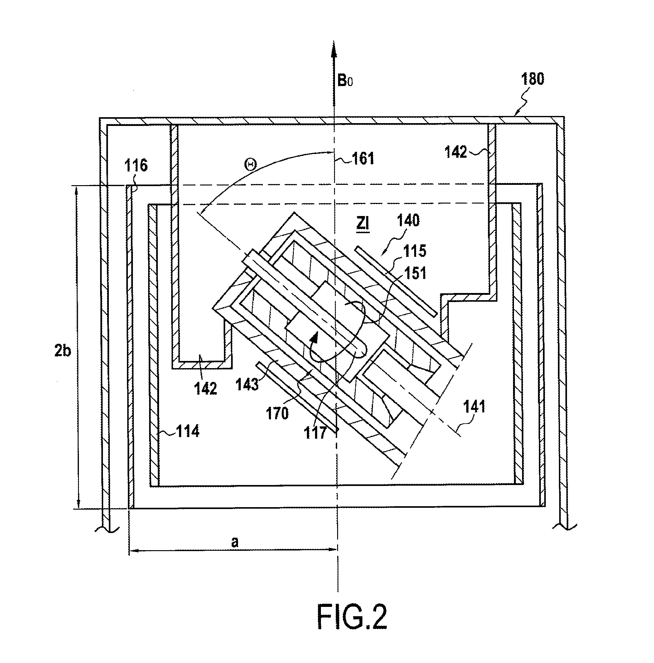
[0054]According to the present invention, magnetic field correction coils or “shim” coils are proposed for taking account respectively of the axial terms Z′1, Z′2, and Z′3, in preferred manner in a spherical harmonic development (SHD), the correction device including said coils being designed specifically for application to a magnetic resonance imaging system having a sample that is inclined relative to the direction of the main magnetic field by being oriented at an angle θ0 that is preferably equal to the magic angle (54.7°).
[0055]These coils are always applied on a cylinder that is coaxial with the hole in the magnet creating the main field, and they may have the same dimensions as sheaths containing correction coils (referred to as “shim sheaths”) that are already in service, thereby enabling them to be used directly in existing installations. They serve to correct directly the terms of the SHD that are associated with the inclined reference frame. This greatly reduces the work of the operator who has to make corrections for irregularities in the main magnetic field created by the magnet.
[0056]Reference is made herein to axial terms Z′1, Z′2, and Z′3 up to degree 3, since they are considered as being the most important, however the invention is naturally not limited in any way to this number, and the method of the invention can be used for calculating the characteristics of coils compensating other terms, of higher degree, or even terms that are not axial.
[0057]A simplified scheme for the application context of the invention is shown in FIG. 1. There can be seen the sample 117 placed along the axis z′, which is at the magic angle relative to the axis z of the magnetic field B0. The sample 117 can turn about this axis z′ at a frequency ωr in order to average out the anisotropic interactions and the residual inhomogeneities of the field. The correction coils 116 (FIG. 2) are designed to perform corrections on the terms of the SHD attached to the inclined coordinate system Ox′y′z′.
[0058]There follows a description of an example of calculating the characteristics of correction coils 116 of the invention.
[0059]The calculation begins by restricting the zone in which currents can exist to a cylindrical surface of radius a and of length 2b. In this context this is a static situation, and thus:
∇·{right arrow over (j)}=0,  (3)
where {right arrow over (j)} is the current density.
[0060]Furthermore, once more because of the static conditions, the following applies at the limits:
{right arrow over (j)}·{right arrow over (n)}=0,  (4)
[0061]where {right arrow over (n)} is the vector normal to the surface.
The current density is thus per unit area and is referred to below as k.
[0062]As a result of the presently imposed geometry, the following cylindrical coordinate system (ρ, φ, z) is adopted with its origin at the center of the cylinder. The cylinder is thus defined by two planes at positions z=b and z=−b and the axis of the cylinder passes through the origin, constituting its axis of symmetry. The axis of the cylinder is the axis of the NMR magnet, i.e. Oz in the laboratory reference frame.
[0063]The current distribution thus takes the general form:
{right arrow over (k)}(z,φ)=kφ(z,φ){right arrow over (uφ)}+kz(z,φ){right arrow over (uz)}  (5)
[0064]It is then possible to apply Biot-Savart's law in order to find the general form of the distribution of the magnetic field induced by the currents. Attention is given here to the component Bz of the field, which is the dominant component in a standard NMR magnet. In order to identify the calculation point of the field, and using cylindrical coordinates in order to integrate over the surface carrying the currents, the following can be written, using Cartesian coordinates (x0,y0,z0), where Oz is along the axis of the magnet:
B z ( x 0 , y 0 , z 0 ) = μ 0 4 π ∫ - b b ∫ - π π ( a - x 0 cos φ - y 0 sin φ ) k φ ( z , φ ) ( a 2 + x 0 2 + y 0 2 + ( z - z 0 ) 2 - 2 a ( x 0 cos φ + y 0 sin φ ) ) 3 2 a φ z ( 6 )
[0065]Thereafter it is important to define appropriately the reference frame (Ox′y′z′) in which the SHD is expressed. With a rotating cylindrical sample 117, it is most advantageous to determine Oz′ as the axis of revolution of the sample. It is well-known that rapid rotation about the axis Oz′ serves to cancel the effect of non-axial terms in the NMR signal. This simplifies the task, which then needs only to adjust the axial terms. It is possible to think in terms of the sample's “own” reference frame.
[0066]The axial terms are none other than the n-derivatives along the axis Oz′ calculated at the origin. This gives:
Z n ′ = 1 n ! ( n B α z ′ n ) O ( 7 )
[0067]The subscript alpha of the term B specifies the component of B along an axis of arbitrary orientation alpha. By way of example, alpha may be x, y, or z. In this specific application where the main field points along the axis z and truncates the transverse components, alpha may thus be z.
It is easy to express uz′ in the reference frame (x,y,z) as a function of its angle of inclination θ and assuming that this inclination is in the plane xOz. This gives:
uz′=cos θuz0+sin θux 0 .  (8)
It is thus possible to write the derivative along Oz′ as:
f z ′ = cos θ f z 0 + sin θ f x 0 ( 9 )
[0068]With the magic angle, this gives:
Z n ′ = μ 0 4 π ∫ - b b ∫ - π π ζ n a φ z ( 10 ) ζ 0 = a ( a 2 + z 2 ) 3 2 k φ ( z , φ ) ( 11 ) ζ 1 = 3 3 ( 3 az + 2 ( 2 a 2 - z 2 ) cos φ ) ( a 2 + z 2 ) 5 2 k φ ( z , φ ) ( 12 ) ζ 2 = 1 2 a ( 2 z 2 - 3 a 2 ) + 2 2 ( 4 za 2 - z 3 ) cos φ + 2 a ( 3 a 2 - 2 z 2 ) cos 2 φ ( a 2 + z 2 ) 7 2 k φ ( z , φ ) ( 13 ) ζ 3 = 3 3 ( - 5 az ( 9 a 2 - 2 z 2 ) ( a 2 + z 2 ) 9 2 + ( 63 2 a 2 z 2 - 36 2 a 4 - 6 2 z 4 ) ( a 2 + z 2 ) 9 2 cos φ + 30 az ( 5 a 2 - 2 z 2 ) ( a 2 + z 2 ) 9 2 cos 2 φ + 10 a 2 ( 4 2 a 2 - 3 2 z 2 ) ( a 2 + z 2 ) 9 2 cos 3 φ ) k φ ( z , φ ) ( 14 )
[0069]As shown above, this gives:
{right arrow over (∇)}·{right arrow over (k)}=0,  (15)
And
{right arrow over (k)}·{right arrow over (n)}=0,  (16)
[0070]These equations imply that k is the rotation of a vector F such that:
{right arrow over (k)}={right arrow over (∇)}×{right arrow over (F)} (17)
{right arrow over (F)}=F(z,φ){right arrow over (u)}z (18)
[0071]F is referred to as the flux function. It can then be shown that the current distribution minimizing dissipated power can be obtained for a value of a given axial term Z′n when the function F is a solution of a Poisson equation. The second member of this equation is given by the constraints set on the field profile, i.e. the relative values desired for the axial terms Z′n (including canceling certain terms, if necessary).
[0072]The flux function F thus minimizes a target function, while complying with the constraints. The target function P′ may be considered as being proportional to the power P dissipated by the Joule effect.
[0073]The following relationships thus apply:
P = a σ e P ′ ( 19 )
P′∫∫S(kφ2+kz2)dφdz (20)
where e is the thickness of the thin conductive layer of electrical conductivity σ.
[0074]This expression needs to be transformed so that it makes use only of the flux function, and the same must be done for the expressions for the constraints. These are the expressions of coefficients of the SHD or of coefficients Zn′, that are to take fixed values or that are not to exceed a given limit in absolute value. Since they are relative to the component Bz of the field produced, they do not depend on kz and they depend linearly on kφ with the following generic form:
Ki′=∫∫Skφfi(φ,z)dφdz (21)
[0075]Once the flux function F has been found, it suffices to trace on the cylinder iso-contours of this function F that are spaced apart in a regular manner between the limits of F (including zero if there is a change of sign), in order to obtain either the positions of loops described by a conductor wire or by a conductive track, or else the positions of cutouts in a conductive plate (e.g. of the copper sheet type).
[0076]FIGS. 3 and 5 show examples of cylindrical coils 116A, 116B, 116C, each generating a magnetic field profile dominated by one axial term Z′n.
[0077]For each figure, the abscissa axis represents the direction parallel to the axis z of the cylinder and the ordinate axis represents angular position on the cylinder. It thus suffices to wrap the figure around a cylinder of appropriate radius in order to obtain the coil. The diagram is to scale and only the proportion between the radius a of the cylinder and its length 2b needs to be kept constant in order to conserve the calculated properties (apart from the magnitude of the term generated per power unit, which decreases when the radius a increases).
[0078]FIG. 3 shows an example of a cylindrical coil 116A generating a field profile dominated by Z′1 and having minimum dissipated power for a given value of Z′1.
[0079]FIG. 4 shows an example of a cylindrical coil 116B generating a field profile dominated by Z′2 and having minimum dissipated power for a given value of Z′2.
[0080]FIG. 5 shows an example of a cylindrical coil 116C generating a field profile dominated by Z′3 and having minimum dissipated power for a given value of Z′3.
[0081]In order to make cylindrical correction coils, it is possible, by way of example, to use insulated copper wire of constant section that may be circular or rectangular and that is glued to the contours as a function of flux. As can be seen in the examples of FIGS. 3 to 5, there exists a set of various iso-contours nested in one another, like contour lines on a map. It is appropriate to go from one iso-contour to a neighboring iso-contour by opening the loop and using a straight segment of wire in a location that is selected to avoid contributing to the main field of the correction device. Thus, the closed loops of the conductor wires superposed on the iso-contours are connected in series, and preferably the connecting segments are arranged parallel to the axis Oz so that they do not create any additional field in this direction.
[0082]The invention also makes it possible to make coils for correcting the gradients Gx, Gy, and Gz from the iso-contours of a flux function, e.g. as shown in FIGS. 8 to 10, which relate respectively to a coil for correcting the gradient Gx, to a coil for correcting the gradient Gy, and to a coil for correcting the gradient Gz. FIGS. 8 and 10 show respective masks 114A, 114B, and 114C for making conductive tracks on a face of a printed circuit so as to constitute winding elements for the gradients Gx, Gy, and Gz. These masks show in particular passages for passing current between the tracks corresponding to neighboring iso-contours, so as to define series connections. It is possible to use a mask on each of the faces of a printed circuit so as to double the effectiveness of the coil. Current passes from one face to the other through vias placed at the centers of the center contours. The gradient-correcting coils serve to increase the linearity of field variation in a fixed direction Oz, in a region of interest, in the same manner as correction coils such as the correction coils 116A, 116B, and 116C seek to make the magnetic field as invariable as possible in the direction Oz in the region of interest.
[0083]FIG. 2 shows an example NMR spectroscopy device comprising a housing 180 inserted in the tunnel of a magnet (not shown) that creates a homogeneous magnetic field B0 in a zone of interest ZI, the magnetic field having an axial component oriented along an axis z 161 of the laboratory.
[0084]A measurement device 140 has a casing 143 connected by support elements 142 to the housing 180. The casing 143 contains a sample 117 of elongate shape oriented along an axis z′141 forming an angle θ relative to the axis z 161 of the main magnetic field B0. The sample 117 may be driven in rotation about its axis z′ (rotary movement 151) by a rotary drive device 170.
[0085]FIG. 2 shows diagrammatically: RF coils 115 (which surround the casing 143 and are coaxial with the sample 117 oriented along the axis z′141); gradient coils 114 (having as their axis the axis z 161 of the laboratory); and cylindrical magnetic field correction coils 116 (of radius a and of length 2b) of characteristics that are determined in the above-described manner while taking into consideration a reference frame Ox′y′z′ associated with the sample 117 and having as their axis the axis z 161 of the laboratory.
[0086]FIG. 6 shows diagrammatically the overall magnetic resonance spectroscopy and imaging system to which the invention is applicable.
[0087]Inside the cylindrical hole of a magnet 118 for creating a main magnetic field having a component Bz oriented along an axis z, an experimentation unit 101 comprises, going from the outside towards the inside: magnetic field correction coils 116 coaxial about the axis z; gradient coils 114 (likewise coaxial about the axis z); and RF coils 115 placed as close as possible to the sample 117.
[0088]The sample 117 of shape that is elongate along an axis z′ is itself inclined at a predetermined angle, e.g. the magic angle, relative to the axis z, as are the RF coils 115 that surround the sample 117.
[0089]An activation unit 102 powers the various coils of the experimentation unit 101 and also receives in return the modulated RF signals from the RF coils 115.
[0090]A control unit 103 (which may be constituted by a computer) comprises a module 136 for communication between a central processor unit 139 and the activation unit 102, random access memory (RAM) units 137, read only memory (ROM) units 138, and a user interface 135. The values of the various signals for supplying by the activation unit 102 are determined by the control unit 103.
[0091]In summary, the space available for a magnetic field source having given characteristics is often very limited in certain directions and leads to making use of current distributions on an imposed geometrical surface. In practice, these surface distributions are made in approximate manner, either by placing filamentary conductors on the surface, or by making appropriate cutouts in thin conductive sheets, or else by using printed circuit techniques.
[0092]For example, magnetic resonance imaging (MRI) machines need to be provided with gradient sources for the main component of the magnetic field in three directions Gx, Gy, and Gz, that are as homogeneous as possible. In most machines, the gradient sources need to be placed inside the empty circular cylinder of the main magnet and to occupy a minimum amount of space therein, which confines them to an annular cylindrical space of small thickness. They can be made by means of copper wire windings of appropriate shape (in helices for Gx and in saddle shapes for Gx or Gy) or also by means of thin tracks (or track portions) made of copper and having cutouts formed therein in order to create current flow channels.
[0093]In these machines, and also in all magnets for producing a magnetic field that is very homogeneous in a given region, it is necessary to provide devices for correcting imperfections of the field resulting from the sources (windings passing currents or magnetized materials) being made imperfectly or from disturbances that may equally well be external to the magnet or internal (the sample and its supports). If the devices, referred to as “shims”, are made using sheaths, then the search for minimum size also leads to using surface distributions that generate a magnetic field in which the component along the direction Oz of the main field presents a given profile in the region of interest.
[0094]The invention, which makes it possible to determine the surface current densities carried by a circular cylinder generating a given profile of the component of the magnetic field along the axis Oz of the cylinder, can be used in the design of various types of corrector systems or field gradient generators.

PUM

no PUM

Description & Claims & Application Information

We can also present the details of the Description, Claims and Application information to help users get a comprehensive understanding of the technical details of the patent, such as background art, summary of invention, brief description of drawings, description of embodiments, and other original content. On the other hand, users can also determine the specific scope of protection of the technology through the list of claims; as well as understand the changes in the life cycle of the technology with the presentation of the patent timeline. Login to view more.
Why Eureka
Try Eureka