Radar Device

Active Publication Date: 2015-12-31
FURUKAWA ELECTRIC CO LTD +1
View PDF5 Cites 10 Cited by
  • Summary
  • Abstract
  • Description
  • Claims
  • Application Information

AI Technical Summary

Benefits of technology

The patent describes a radar device that can reduce the impact of its structure, such as a bumper, on the transmission and reception of signals. This is achieved by using a dummy antenna to reduce the frequency of high-level signals, which can interfere with the transmission and reception process. This allows for better utilization of the radar device's antenna.

Problems solved by technology

In the example of FIG. 18, the reflected waves from the bumper B and the reflected wave from the object are not temporally overlapped, but, in a case where they overlap, the reflected waves from the bumper B becomes a noise and the radar device 1A cannot detect the object accurately.
With the technique described in Patent Literature 1, since it is necessary to form a complicated geometry at the back side of the bumper, there is a drawback that a production cost of the bumper is increased.
With the technique described in Patent Literature 2, since the transmission frequency is adjusted, there is a drawback that it is not applicable to a radar having a fixed transmission frequency.
With the technique described in Patent Literature 3, there is a drawback that it is not possible to reduce an influence of reflection at an aperture of an array antenna.

Method used


Image

  • Radar Device
  • Radar Device
  • Radar Device

Examples


first embodiment

(B) First Embodiment

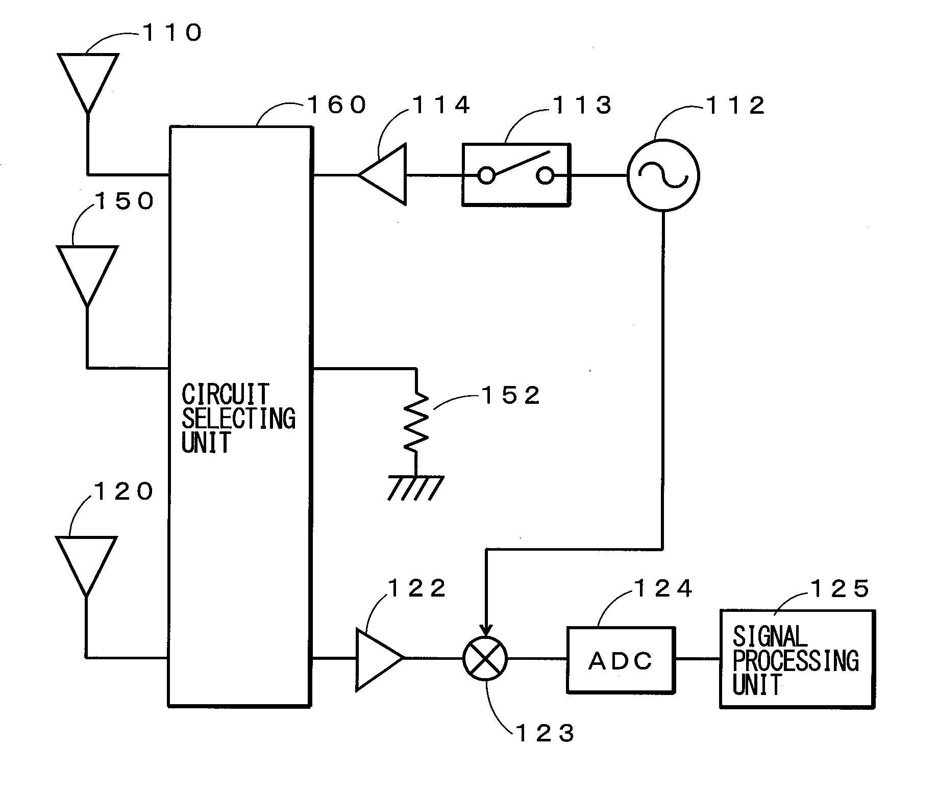
[0079]The first embodiment of the present disclosure will be described. In the first embodiment, configurations of the substrate 10 and the radome 20 are similar to those shown in FIGS. 2 and 3, but an electrical configuration differs. FIG. 7 is a block diagram showing an example of the electrical configuration of the first embodiment. Note that, in this figure, parts corresponding to those shown in FIG. 1 are accompanied by the same reference numerals and descriptions thereof are omitted. As compared to FIG. 1, the first embodiment shown in FIG. 7 has a switch 153 as the circuit selecting unit 160. The switch 153 has a terminal connected to the dummy antenna 150 and two selective terminals, in which one of the selective terminals is connected to an output terminal of the amplifier 114 and the other selective terminal is connected to one of the terminals of the resistance element 152. The switch 153 is controlled to select an output terminal of the amplifier 114 ...

second embodiment

(C) Second Embodiment

[0087]The second embodiment of the present disclosure will be described. In the second embodiment, configurations of the substrate 10 and the radome 20 are similar to those shown in FIGS. 2 and 3, but an electrical configuration differs. FIG. 9 is a block diagram showing an example of the electrical configuration of the second embodiment. Note that, in this figure, parts corresponding to those shown in FIG. 1 are accompanied by the same reference numerals and descriptions thereof are omitted. As compared to FIG. 1, the second embodiment shown in FIG. 9 has a switch 153 as the circuit selecting unit 160. The switch 153 has a terminal connected to the dummy antenna 150 and two selective terminals, in which one of the selective terminals is connected to a terminal of the resistance element 152 and the other selective terminal is connected to an input terminal of the amplifier 122. The switch 153 is controlled by a control unit, not shown, to select an output of the...

third embodiment

(D) Third Embodiment

[0095]The third embodiment of the present disclosure will be described. In the third embodiment, configurations of the substrate 10 and the radome 20 are similar to those shown in FIGS. 2 and 3, but an electrical configuration differs. FIG. 11 is a block diagram showing an example of the electrical configuration of the third embodiment. Note that, in this figure, parts corresponding to those shown in FIG. 1 are accompanied by the same reference numerals and the descriptions thereof are omitted. As compared to FIG. 1, the third embodiment shown in FIG. 11 has a switch 154 as the circuit selecting unit 160. The switch 154 has a terminal connected to the dummy antenna 150 and three selective terminals, in which one of the selective terminals arranged upper most in the figure is connected to an output terminal of the amplifier 114, a middle selective terminal is connected to the resistance element 152, and a selective terminal arranged lower most in the figure is con...


PUM


Abstract

A radar device that transmits a high frequency signal and detects an object by a reflected wave that is reflected by the object includes a transmitting antenna that transmits the high frequency signal, a receiving antenna that receives a reflected wave that is transmitted by the transmitting antenna and reflected by the object, and a dummy antenna that attenuates a reflected wave that is reflected by a structure arranged on a transmission path of the high frequency signal. The dummy antenna is configured be selectable as an antenna having another function.

Description

CROSS REFERENCE TO RELATED APPLICATIONS[0001]This is a continuation application of International Patent Application No. PCT / JP2013 / 062654 filed Apr. 30, 2013, the full content of which is hereby incorporated by reference in its entirety.BACKGROUND[0002]1. Technical Field[0003]The present disclosure relates to a radar device.[0004]2. Background Art[0005]A vehicle-mount radar device of the related art is, for example, arranged on a back side of a bumper of a vehicle and can detect a position, a direction, a distance, a velocity, etc., of an object by transmitting a transmission wave that penetrates through the bumper, receiving a reflected wave that is reflected by an object, and analyzing a relationship between the transmission wave and the reflected wave.[0006]Although the bumper is constituted by a member made of a resin or the like that is permeable to electromagnetic waves, depending on a positional relationship between an antenna and the bumper, there may be a case in a pulse ra...

Claims


Application Information

Patent Timeline
IPC IPC(8): G01S7/03G01S13/931
CPCG01S7/038G01S13/931G01S2007/027G01S2013/9389H01Q1/3283H01Q17/00H01Q19/005H01Q19/021H01Q21/065G01S7/02G01S7/03G01S2013/93275G01S7/027
Inventor ISHIDA, YOSHIYUKIMATSUSHIMA, SADAO
Owner FURUKAWA ELECTRIC CO LTD
Why Eureka
Try Eureka