Assembly for a video endoscope

Active Publication Date: 2015-12-31
RICHARD WOLF GMBH
View PDF4 Cites 29 Cited by
  • Summary
  • Abstract
  • Description
  • Claims
  • Application Information

AI Technical Summary

Benefits of technology

[0004]Against this background, it is an object of the invention to design a subassembly which is of the known type and is for a video endoscope, such that one the one hand an as small as possible construction size with respect to the specified

Problems solved by technology

However, the smaller the diameter of the endoscope, the longer becomes the construction length in the distal end region, which is particularly dis

Method used


Image

  • Assembly for a video endoscope
  • Assembly for a video endoscope
  • Assembly for a video endoscope

Examples


Example

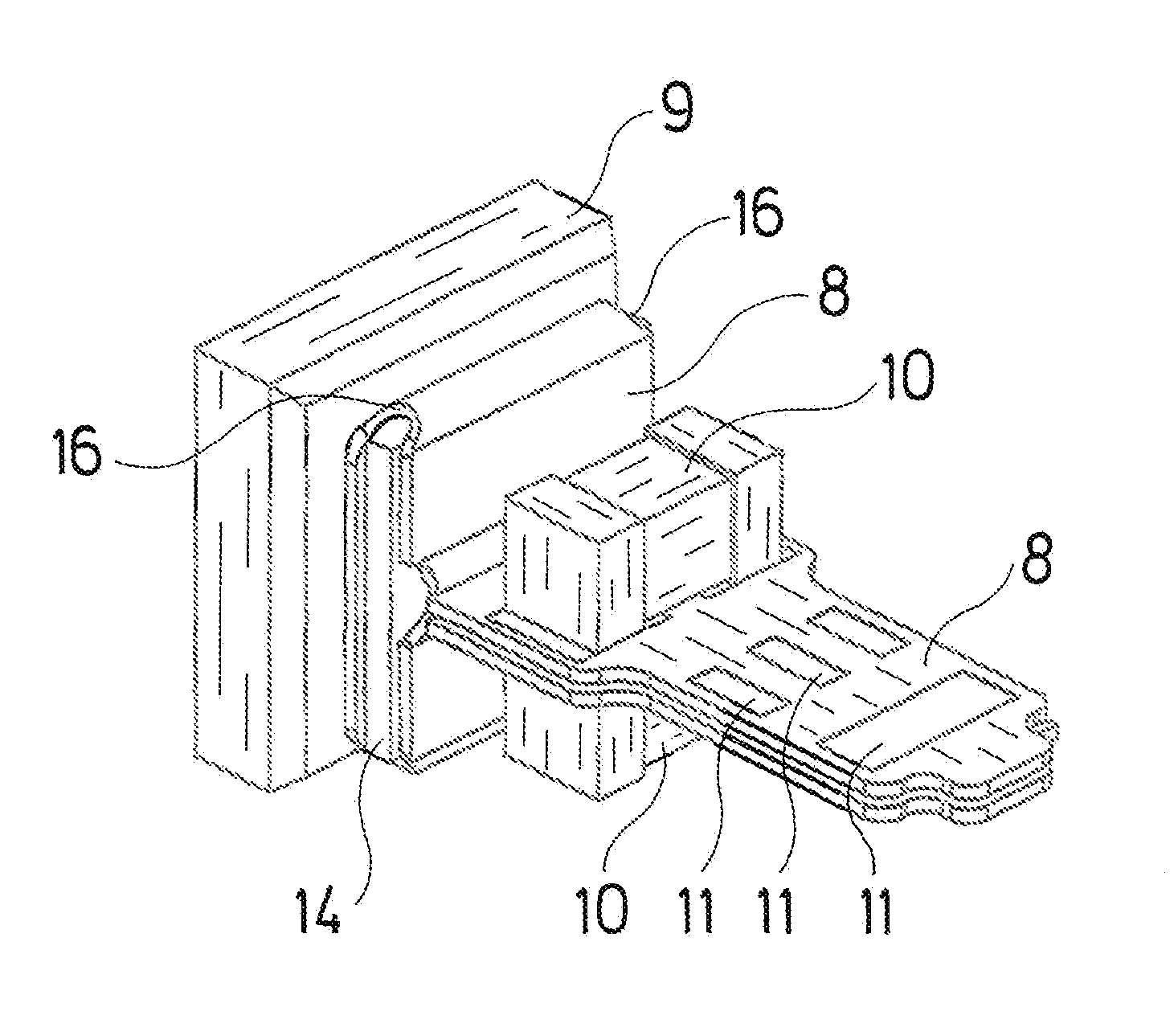
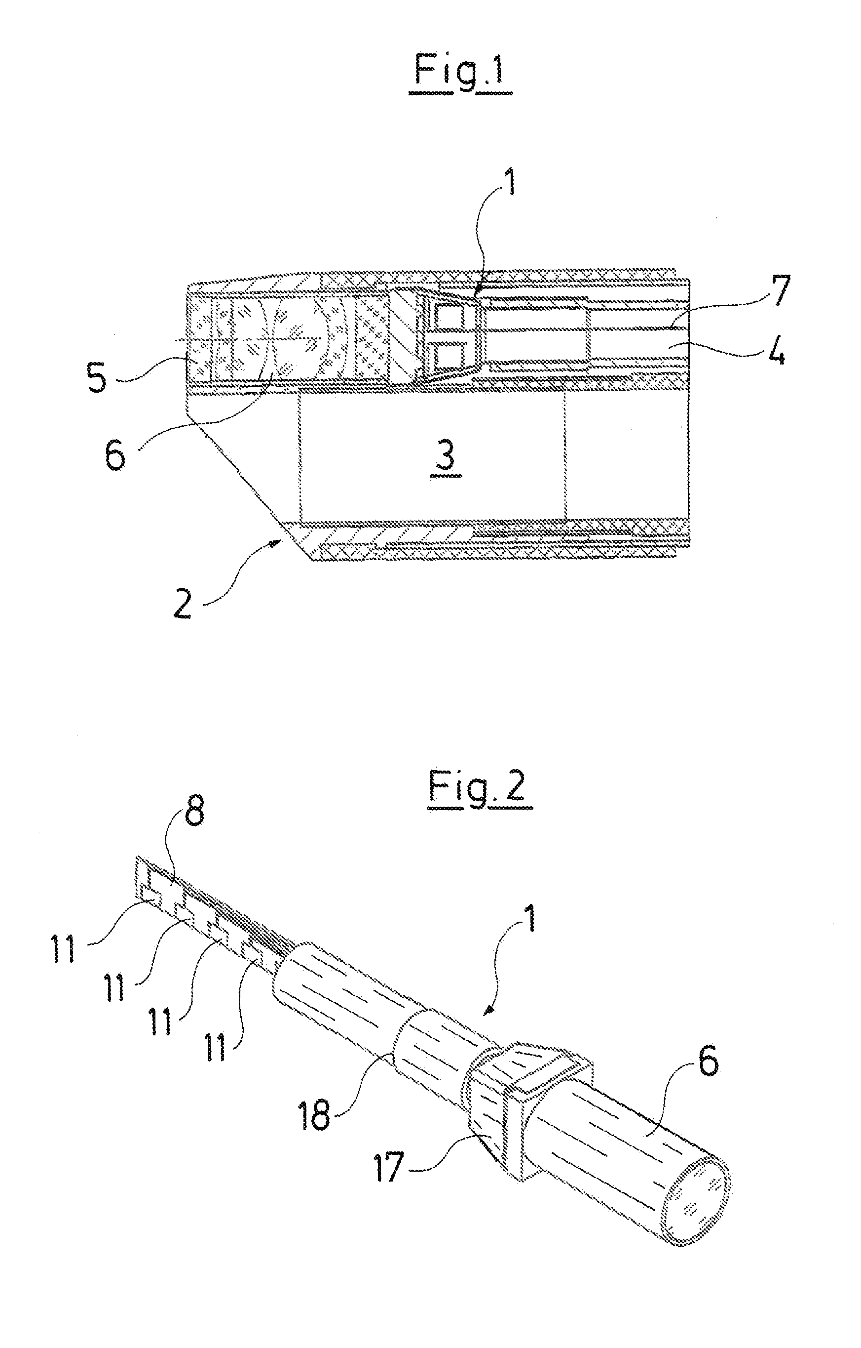
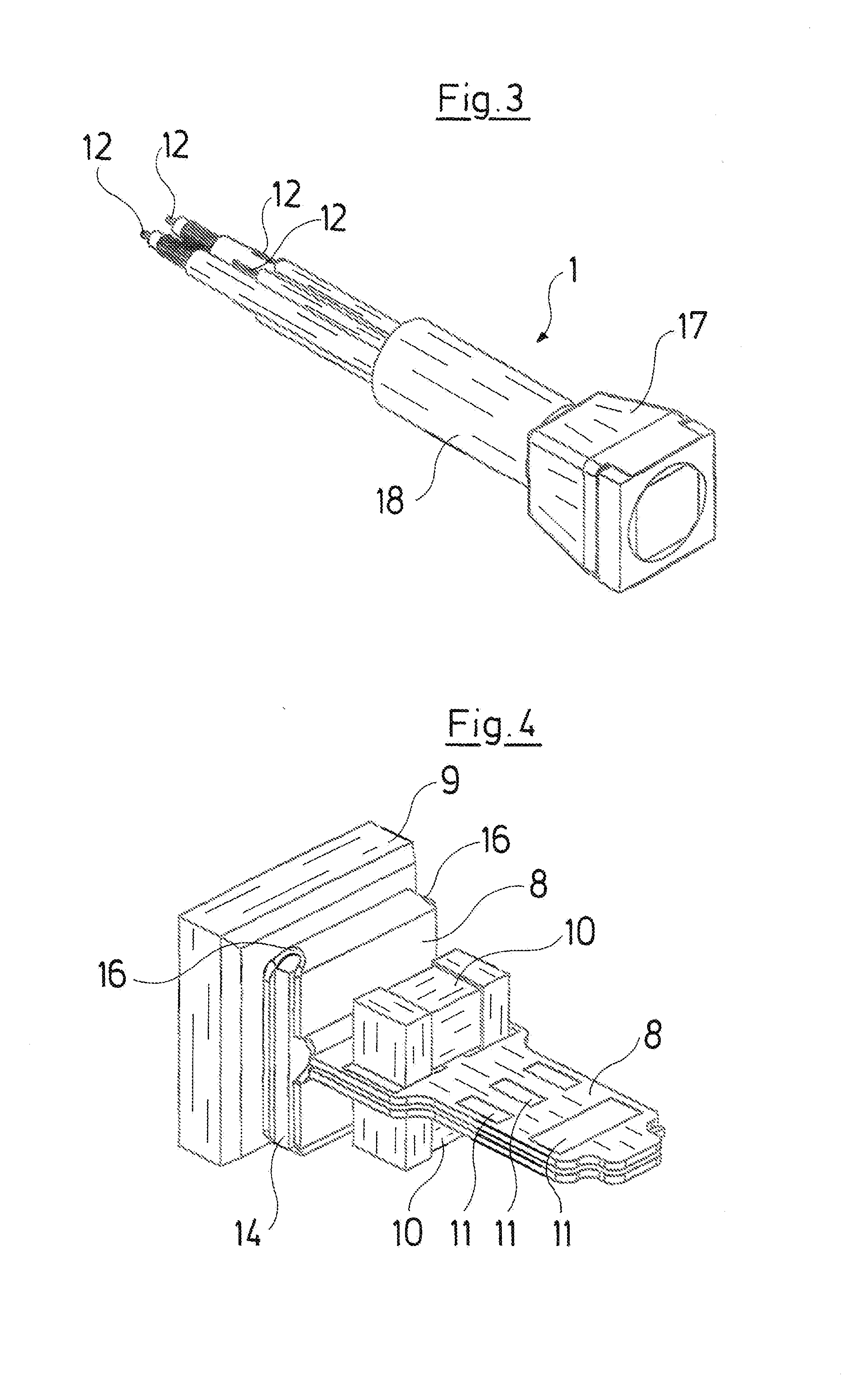
[0035]The distal end of a video endoscope is represented in a longitudinal section by way of example in FIG. 1, and this distal end is equipped with a subassembly 1 according to the invention. In the figure, one can see the distal end section 2 with a working channel 3 and an optics channel 4 which is closed off at the end side by way of a window 5, e.g. of sapphire, which terminates the channel in a fixed and sealed manner. A lens 6 connects to this window 5 at the proximal side and is fixedly connected to the distal end of the subassembly 1 whose electrical connection cables in the form of individually insulated wires 12 surrounded by a shielding flexible sleeve and in the form of a cable 7 which is only schematically represented in FIG. 1 are led to the proximal instrument end.

[0036]The subassembly 1 is represented by way of FIG. 2 (with lens) in a modified form and in FIG. 3 (without lens).

[0037]Such a subassembly 1 is constructed on a longitudinally extended, highly flexible ci...


PUM


Abstract

A subassembly for a video endoscope with a picture-recording sensor (9) which is electrically conductively arranged on a flexible circuit board (8) which next to the sensor (9) is bent at least at one side and is conductively connected to at least one electrical cable proximally of the sensor (9).

Description

CROSS REFERENCE TO RELATED APPLICATIONS[0001]This application is a United States National Phase Application of International Application PCT / EP2014 / 052914 filed Feb. 14, 2014 and claims the benefit of priority under 35 U.S.C. §119 of German Patent Application 10 2013 202 516.5 filed Feb. 15, 2013 the entire contents of which are incorporated herein by reference.FIELD OF THE INVENTION[0002]The invention relates to a subassembly for a video endoscope, with a picture-recording (image capturing) sensor.BACKGROUND OF THE INVENTION[0003]With regard to video endoscopes, it is counted as belonging to the state of the art to place a subassembly consisting of a picture sensor, capacitor, circuit board and cable in the distal region directly behind the lens (objective). The picture which is produced by the lens is projected onto the sensor and the signals are led via cables led through the endoscope shank, to the electronics which are arranged at the proximal side. Such endoscopes or technosco...

Claims


Application Information

Patent Timeline
IPC IPC(8): G02B23/24A61B1/005A61B1/00H01L27/146A61B1/05
CPCH04N5/2251H04N5/2253H04N2005/2255A61B1/00018H01L27/14601A61B1/00131A61B1/005G02B23/2407G02B23/2484A61B1/05H04N23/50H04N23/555H04N23/54
Inventor HANDTE, RENÉHEIMBERGER, RUDOLF
Owner RICHARD WOLF GMBH
Why Eureka
Try Eureka