Rotary drive assembly for a drill rod

Active Publication Date: 2010-08-10
EURODRILL
View PDF12 Cites 11 Cited by
  • Summary
  • Abstract
  • Description
  • Claims
  • Application Information

AI Technical Summary

Benefits of technology

[0008]The object of the invention is to provide a rotary drive assembly which can be employed in a great variety of ap

Problems solved by technology

However, such drive assemblies can have a comparatively large constructional length in the direction of the dri

Method used


Image

  • Rotary drive assembly for a drill rod
  • Rotary drive assembly for a drill rod

Examples


Example

[0041]Elements having the same function are designated throughout the Figures with the same reference signs.

DETAILED DESCRIPTION OF THE PREFERRED EMBODIMENTS

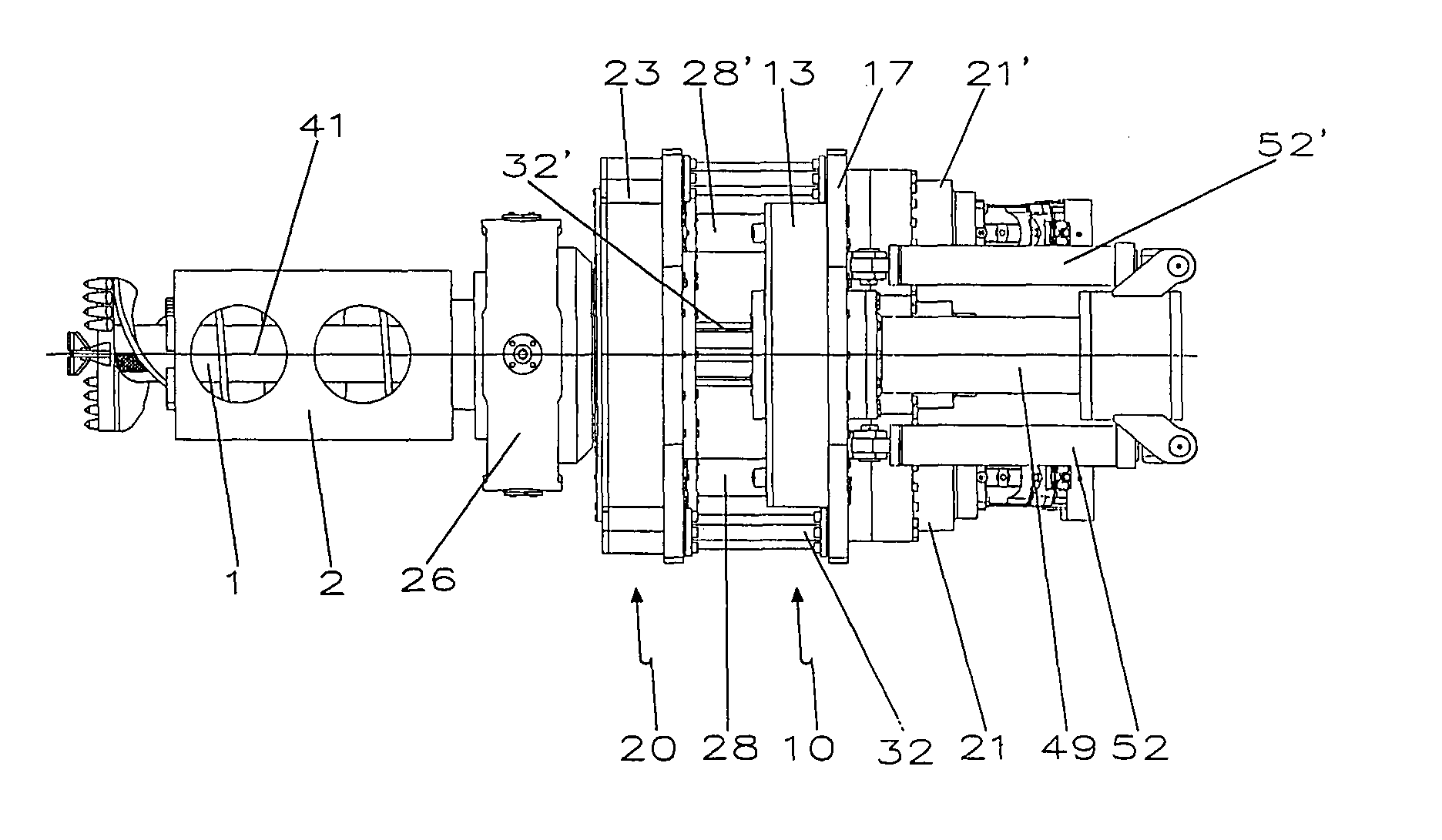
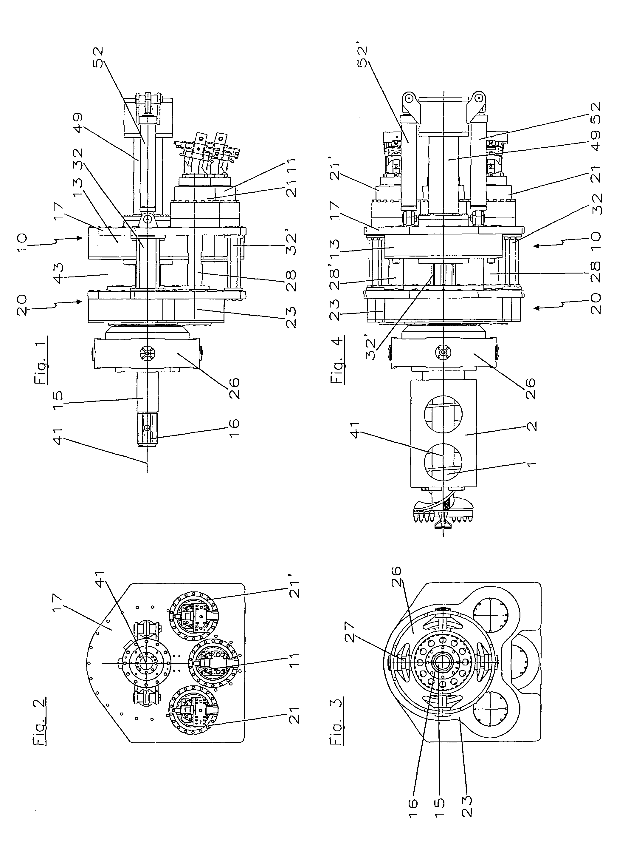
[0042]An embodiment of a rotary drive assembly according to the invention is shown in FIGS. 1 to 4. The rotary drive assembly has a first gear unit 10 to operate an inner rod 1 depicted in FIG. 4 in a rotating manner and a second gear unit 20 to operate an outer tube 2 depicted in FIG. 4 in a rotating manner, in which case the outer tube 2 encompasses the inner rod 1 coaxially. Both gear units 10, 20 are designed as spur gears.

[0043]The two gear units 10, 20 are arranged in an offset manner in the direction of the drilling axis 41 that extends longitudinally and centrally through the inner rod 1 and the outer tube 2. The first gear unit 10 has a box-shaped housing 13 and the second gear unit 20 has a box-shaped housing 23. The two housings 13, 23 are kept at a distance by means of struts 32, 32′ that extend parallel to the drill...


PUM


Abstract

The invention relates to a rotary drive assembly for a drill rod having an outer tube and an inner rod extending at least in sections inside the outer tube, comprising a first gear unit having at least a first drive unit for driving the inner rod in a rotating manner and a second gear unit, which is offset to the said first gear unit in the longitudinal direction of the drill rod and has at least a second drive unit for driving the outer tube in a rotating manner. In accordance with the invention provision is made for the second drive unit to be spaced from the second gear unit and for the second drive unit to be arranged adjacent to the first drive unit on the first gear unit.

Description

BACKGROUND OF THE INVENTION[0001]1. Field of the Invention[0002]The invention relates to a rotary drive assembly for a drill rod having an outer tube and an inner rod extending at least in sections inside the outer tube, in particular for double-head and / or superposed drilling.[0003]2. Related Art[0004]A rotary drive assembly of such type includes a first gear unit having at least a first drive unit for driving the inner rod in a rotating manner and at least a second gear unit, which is arranged offset to the said first gear unit in the longitudinal direction of the drill rod and has at least a second drive unit for driving the outer tube in a rotating manner.[0005]Rotary drive assemblies for double-head drilling devices are known that have two gear units arranged one behind the other in the longitudinal direction of the drill rod, in which case one of the gear units serves for the rotating operation of the inner rod while the other serves for the rotating operation of the outer tub...

Claims


Application Information

Patent Timeline
IPC IPC(8): E21B4/04
CPCE21B3/02E21B7/002
Inventor UELHOFF, HENRIKPIKOWSKI, ANDREAS
Owner EURODRILL
Why Eureka
Try Eureka