Methods and systems for server power line communication

Active Publication Date: 2015-12-31
INTEL CORP
View PDF13 Cites 33 Cited by
  • Summary
  • Abstract
  • Description
  • Claims
  • Application Information

AI Technical Summary

Problems solved by technology

However, since systems are not often used to capacity, a smaller power supply may detect an abnormal condition and generate an interrupt to signal the servers to throttle back until the power comes back into an acceptable range.

Method used


Image

  • Methods and systems for server power line communication
  • Methods and systems for server power line communication
  • Methods and systems for server power line communication

Examples


example embodiments

[0059]The following examples pertain to further embodiments.

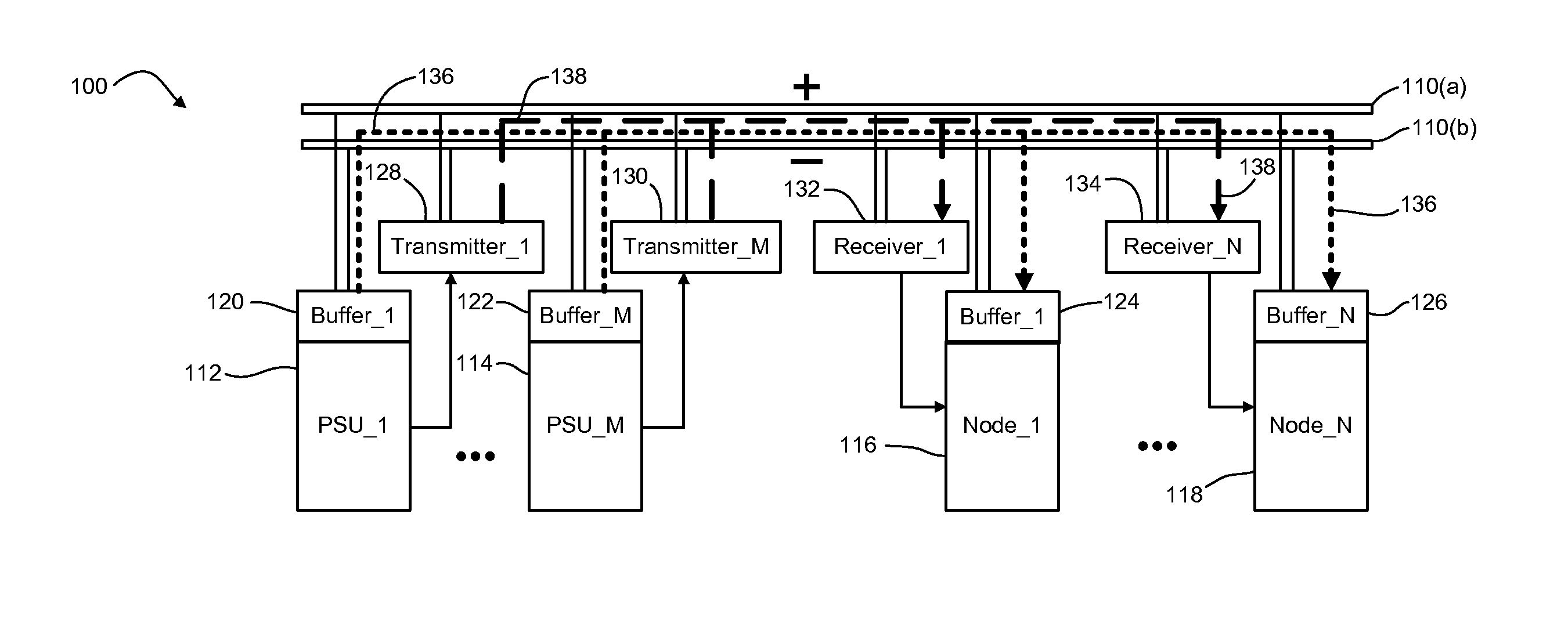
[0060]Example 1 is a server system including a common power bus, a power supply to provide direct current (DC) power through the common power bus, at least one node comprising a processor to receive the DC power through the common power bus, a transmitter capacitive coupled to the common power bus to transmit a power information signal from the power supply through the common power bus, and at least one receiver capacitive coupled to the common power bus to receive the power information signal transmitted by the transmitter. The at least one receiver also to provide the received power information signal to the at least one node. The example server system also includes a plurality of buffers respectively coupled between the common power bus and each of the power supply and the at least one node. The plurality of buffers to separate paths for high frequency and low frequency currents, and to provide high frequency insulation ...


PUM


Abstract

A server system includes a common power bus, a power supply to provide direct current (DC) power through the common power bus, at least one node including a processor to receive the DC power through the common power bus, a transmitter capacitive coupled to the common power bus to transmit a power information signal from the power supply through the common power bus, and at least one receiver capacitive coupled to the common power bus to receive the power information signal transmitted by the transmitter and to provide the received power information signal to the at least one node. A plurality of buffers respectively coupled between the common power bus and each of the power supply and the at least one node provide path separation for high frequency and low frequency currents.

Description

TECHNICAL FIELD[0001]This disclosure generally relates to power supplies for servers and other computing devices and, more particularly, to communication and power management in a multi-node system.BACKGROUND[0002]Server systems having redundant power arrangements may incorporate two or more power supply modules that are configured to continuously supply maximum power to the system when either an alternating current (AC) power source or one of the modules fails. For example, if the peak workload power consumed from a conventional redundant power subsystem containing two power modules is PMAX, each of the modules may typically be rated at PMAX or greater to maintain system operation when a failure occurs.[0003]Power supplies are typically sized larger to deliver the maximum power PMAX that the system may need. However, since systems are not often used to capacity, a smaller power supply may detect an abnormal condition and generate an interrupt to signal the servers to throttle back ...

Claims


Application Information

Patent Timeline
Patent Type & Authority Applications(United States)
IPC IPC(8): H04B3/54H04B3/56
CPCH04B3/546H04B3/548H04B3/56H04B2203/547H04B2203/5495G06F1/26G06F1/3209Y04S40/146H04H20/38H04L47/50G06F1/3206H04B2203/5483Y04S40/121
Inventor GRIFFITH, BRIAN J.VOGMAN, VIKTOR D.SONG, JUSTIN J.
Owner INTEL CORP
Why Eureka
Try Eureka