
Modular Connected Headrest

a headrest and module technology, applied in the field of headrests, can solve the problems of inability to improve the safety of the driver and passenger occupants, the difficulty of interconnection between the current apparatus providing video/audio imaging and the vehicle performance monitoring device, and the structural difficulty of placing the imaging device or camera, so as to achieve the effect of reducing the number of antennas

Inactive Publication Date: 2015-12-31
MOBILE VIDEO COMPUTING SOLUTIONS LLC
View PDF3 Cites 17 Cited by
  • Summary
  • Abstract
  • Description
  • Claims
  • Application Information

AI Technical Summary

Benefits of technology

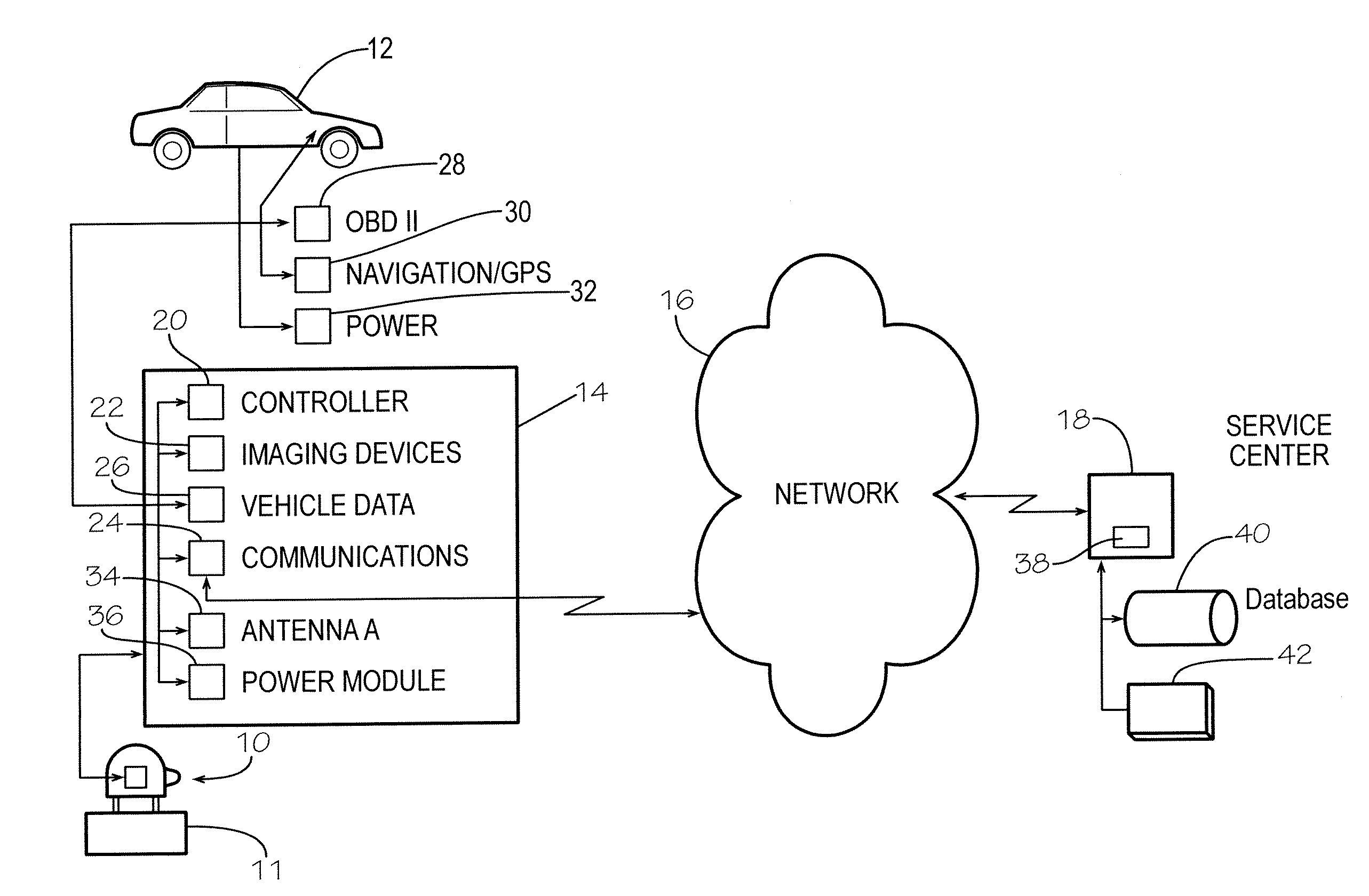
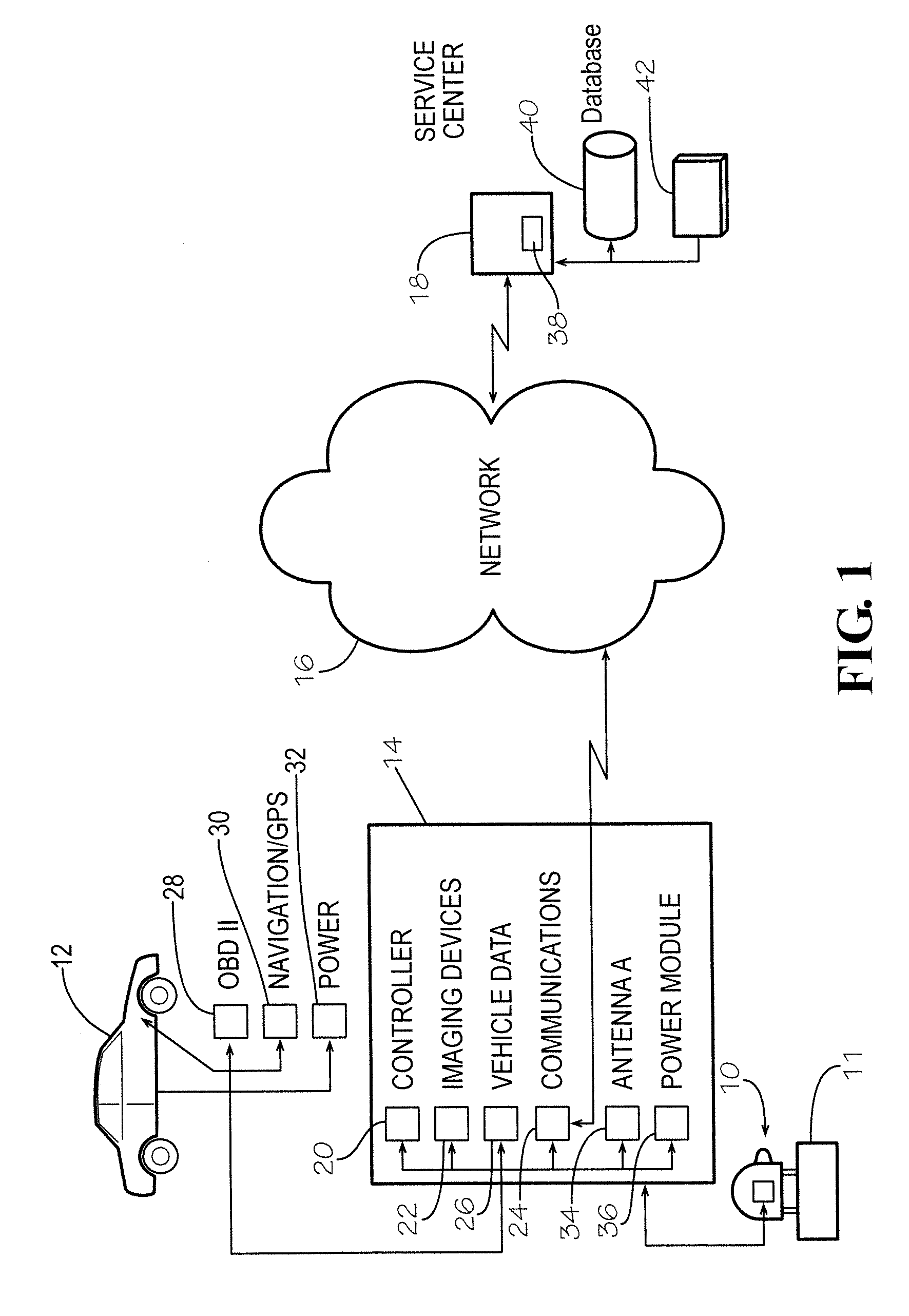
The present invention is a modular camera recording connecting headrest that can be installed in both original equipment manufacturer (OEM) vehicles and retro-fit vehicles. The headrest incorporates components for imaging, data collection, and data communication, including cameras, recorders, data interface devices, and other equipment. It offers a simple and safe solution for recording motor vehicle operational information. The modular headrest can also connect wirelessly to networks and provides an attractive and cost-effective solution for imaging and memorializing motor vehicle information.

Problems solved by technology

While video imaging devices have been available for use in motor vehicles to provide a reasonable approximation of the driver's viewpoint during operation of the motor vehicle, there are drawbacks to the use of such.
Installation and integration of current apparatus that provides video / audio imaging and interconnections with vehicle performance monitoring devices is difficult for new vehicle production, and particularly for aftermarket retrofit into a motor vehicle.
The difficulties arise from the need to maintain the cockpit safety constructs for motor vehicle driver and passenger occupancy and operation yet provide effective capturing of the vehicle interior, vehicle operational data such as is available for dashboard display, and driver local and remote distant views.
This is due to the installation of active safety systems within the frontal strike zones of motor vehicles, which systems occupy previously available space, such as in front of the rear view mirror.
Placement of imaging device or camera becomes structurally difficult and tends to be off-center such that a second or multiple imaging devices are necessary to provide reasonable viewpoint imaging.
In addition to labor and installation time, there is also the issue of creating appropriate wiring harnesses necessary to achieve the important imaging and data collection features for appropriate recordation of vehicle operation.
Further, the recent rapid adoption of global positioning systems (GPS) location and tracking, text messaging, and electronic mail, particularly via smart mobile communication devices, has not translated into improvements in the safety of the driver and passenger occupants.
At least two issues—driver distraction and loss of sight—may be attributed to accidents.
The electronics available to a driver include radio systems (both conventional and satellite), CD, GPS, network interconnectivity, mobile cellular telephone, and other, may lead to driver distraction in operation of such devices.
Indeed, many states restrict driver use of cellular phones during motor vehicle operations.
Repositioning information into a “far view” presentation window or to a heads-up display has been costly and is generally limited as to the scope of information that is displayable (such as limited to motor vehicle speed).
There are challenges in deploying video cameras and data access and information systems as standardized equipment packages due to the variables and designs involved with the interior of a motor vehicle.
The field of view problems also arises in obtaining not just the driver's view but those of other occupants, and the suitable positioning of imaging devices to collect such viewpoints.
The lack of uniform structures across manufacturer platforms for motor vehicles (and multi-manufacturer platforms), presents implementation issues but the present need may lead to further joint agreements on standardized structures.
Installation presents difficulties (both OEM and aftermarket retro-fit) particularly utilizing cables for power, control, and data communication, as well as device and equipment housings, secure mountings, and placement.
Around these issues also revolves the attendant safety requirements for motor vehicle occupants, as well as installation labor and time.

Method used


Image

  • Modular Connected Headrest
  • Modular Connected Headrest
  • Modular Connected Headrest

Examples


first embodiment

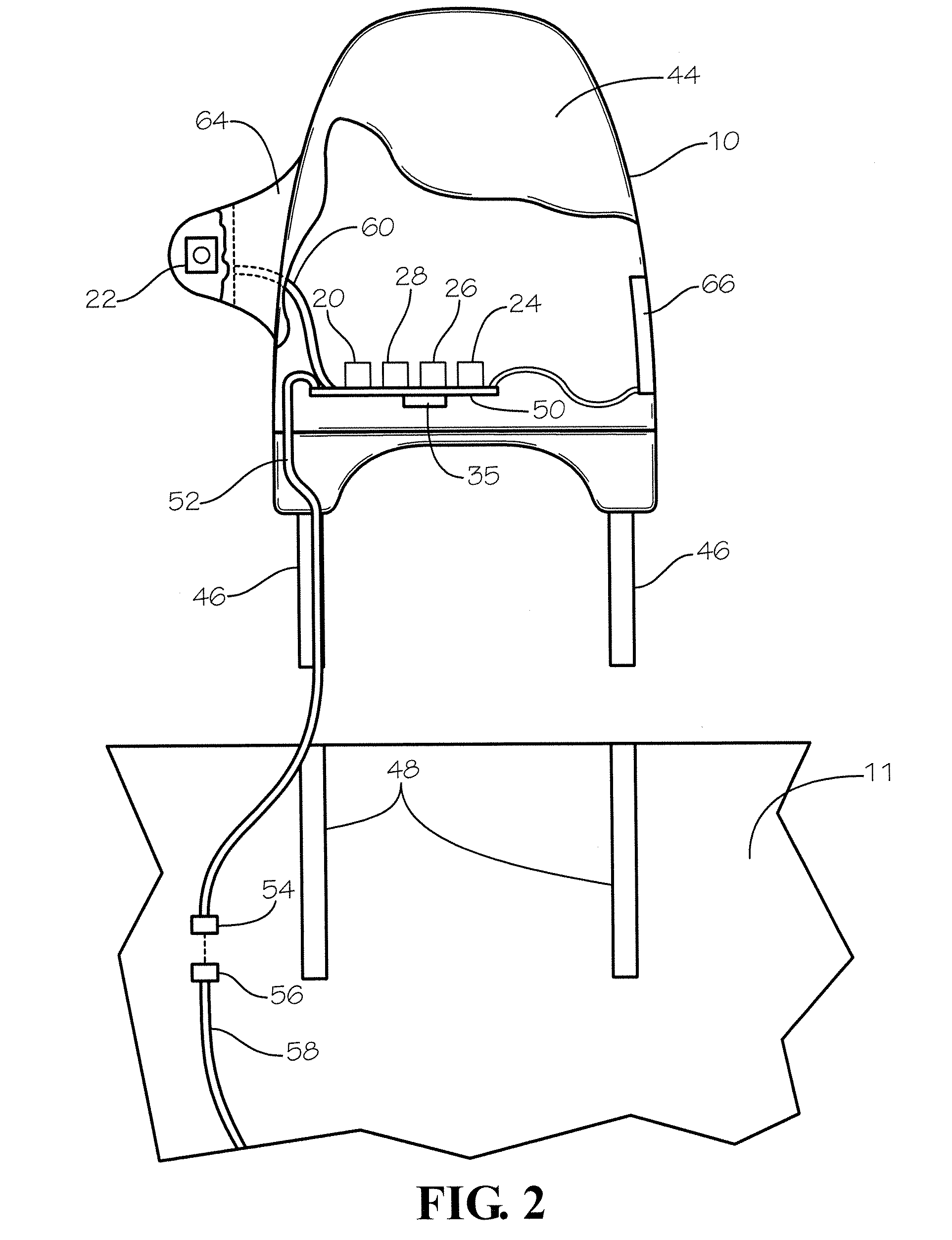
[0018]FIG. 2 illustrates in front view the modular connected headrest 10 that engages the seat 11 of the motor vehicle 12. The headrest 10 may be a conventional OEM headrest modified to incorporate the structural components of the modular connected headrest in accordance with the present invention. The headrest 10 includes a head cushioning front face 44 and opposing back face with opposing sides. A pair of tubular members 46 extend from the headrest frame for being received in aligned support sleeves 48 mounted in the seat 11.

[0019]A board 50 mounts rigidly within the headrest 10. The various required and optional components attach to the board 50, including the power module 36 that distributes current to operate the components. A wiring harness 52 attaches the board 50 for supplying current to the power module 36. The wiring harness 52 extends through one of the tubular members 46 into the back of the seat 11. An opposing distal end of the wiring harness 52 detachably connects wit...

second embodiment

[0021]FIG. 3 illustrates in side view the modular connected headrest 10 for the motor vehicle illustrated in FIG. 2. In this embodiment, the external antenna 66 mounts to a side of the headrest opposing the arm 64. The antenna 66 includes one or more global positioning satellite (GPS) antenna, cellular, wi-fi, or other communications transmitting and receiving apparatus for communicating signals for video, audio, digital image, vehicle operational data, and other sensed and imaged information relating to the motor vehicle, its operation in time periods, and the circumstantial surroundings such as roadway, traffic, weather conditions proximate the motor vehicle during operation.

[0022]FIG. 4 illustrates in partial cut-away view a second embodiment of a modular connected headrest 80 for aftermarket retro-fit installation in a motor vehicle. The modular connected headrest 80 provides an open-ended sleeve 82, helmet, or tube that receives the conventional headrest 84 installed by the OEM...


PUM


Abstract

A motor vehicle usage tracking system for monitoring, evaluating, and reporting on operations of motor vehicles each having a modular connected headrest with an imaging device for imaging in a viewpoint from a driver's seating position and communicating with a data bus in the motor vehicle for the operational data correlated with the imaging and communicated to the servicer having an analyzer configure for evaluating and reporting on motor vehicle operations. An aftermarket sleeve is disclosed for retro-fit installation of the motor vehicle tracking device.

Description

[0001]The present application claims benefit of U.S. Provisional Patent Application Ser. No. 62 / 019,166, filed Jun. 30, 2014, which is incorporated herein by reference in its entirety.TECHNICAL FIELD[0002]The present invention relates to headrests for seats in motor vehicle. More particularly, the present invention relates to apparatus and methods for driver point of view imaging during operation of motor vehicles with headrests for seats populated for imaging, correlating vehicle operational data and communicating correlated images and operational data to a servicer for monitoring, evaluation and reporting.BACKGROUND OF THE INVENTION[0003]While video imaging devices have been available for use in motor vehicles to provide a reasonable approximation of the driver's viewpoint during operation of the motor vehicle, there are drawbacks to the use of such. Installation and integration of current apparatus that provides video / audio imaging and interconnections with vehicle performance mo...

Claims


Application Information

Patent Timeline
Patent Type & Authority Applications(United States)
IPC IPC(8): H04N7/18B60N2/58B60N2/48H04N5/225
CPCH04N7/183H04N7/181H04N5/225B60N2/879G07C5/008G06K9/00832H04N5/23206G06V20/59H04N23/661H04N23/00
Inventor WATKINS, D SCOTTLAMONT, JOHN
Owner MOBILE VIDEO COMPUTING SOLUTIONS LLC
Learn More