Structure and Method For Recognizing Information on a Filter Installed in an Air Purifier of a Respirator

a filter unit and information recognition technology, applied in the field of air purifiers of respirators, can solve the problems of filter units, low load rate, and possible errors, and achieve the effect of preventing errors, failures, and malfunctions

Inactive Publication Date: 2016-01-07
OTOS WING
View PDF4 Cites 39 Cited by
  • Summary
  • Abstract
  • Description
  • Claims
  • Application Information

AI Technical Summary

Benefits of technology

[0027]It is an aspect of the present invention to provide a structure and method for recognizing information on a filter unit mounted on an air purifier of a respirator, in which the air purifier and the filter unit of the respirator which filters polluted external air and supplies purified air to a worker are wirelessly interconnected in such a way that a control unit of the air purifier may provide the worker with the information on the filter unit such as a type, a load rate depending on a blockage degree of the filter unit, a final operation time, a residual operation time, and a replacement time of the filter unit through information data transmitted from the filter unit. It is possible to precisely recognize the filter unit appropriate for a workplace and a work environment, thereby preventing an error, failure, and malfunction of the filter unit and simultaneously with continuously working.
[0028]It is another aspect of the present invention to provide a structure and method for recognizing information on a filter unit mounted on an air purifier of a respirator, in which the air purifier and the filter unit are wirelessly interconnected through radio frequency identification (RFID), wireless fidelity (Wi-Fi), near field communication (NFC), Bluetooth, or Zigbee to detect a type of a filter, to recognize information of the detected filter such as an operation time and life thereof by counting an operation time of the filter, and to allow a wearer to recognize the information.
[0029]It is still another aspect of the present invention to provide a structure and method for recognizing information on a filter unit mounted on an air purifier of a respirator, in which information data of the filter unit such as a serial number, a filter type, a final operation time, a residual time, and a replacement time of the filter unit are stored in a control unit when an operation of the filter unit is finished. When the filter unit is mounted in the air purifier to use, the air purifier and the filter unit are wirelessly interconnected to transmit the information data of the filter unit such as the serial number to the air purifier. Based on this, the control unit detects information data of the same type of the filter unit from previously stored information data of the filter unit, and counts from the final operation time. When the operation of the filter unit is finished, information data on the serial number, counted final operation time, changed residual time, etc. is stored in the control unit, thereby allowing a worker to accurately recognize a replacement time of the filter unit. Due to this, the worker may be effectively protected from harmful gases and fine dust such as metal dust and metal fumes, thereby preventing safety accidents in advance and improving work efficiency.

Problems solved by technology

Accordingly, when the type of the filter unit mounted and installed in the air purifier is not input and set, a malfunction and error may occur.
That is, when the particle removal filter is mounted in the installation space of the air purifier and then the worker inputs and sets a type as the odor removal filter through the LCD panel of the air purifier, since the particle removal filter having a lower filtration density than the odor removal filter is recognized as the odor removal filter, a load rate is sensed low and the occurrence of an abnormality and an error in the filter unit recognized not to perform purification and filtering of polluted external air is sensed.
Due to this, inconveniences in which the worker replaces the filter unit according to an abnormality and error text displayed on the LCD panel may occur and work efficiency is deteriorated, for example, a working time increases.
However, as described above, when the input and setting of the worker are wrong and then an error and a malfunction occur in the air purifier due thereto, not only an unnecessary expense occurs, for example, the filter unit which does not pass the reference life is exchanged and replaced but also the environment becomes polluted due to the discarded filter unit.
Also, when it is required to exchange and replace the filter unit due to an abnormality of the filter unit while working, the working is stopped and the filter unit is exchanged and replaced, and simultaneously, the type of the filter unit is input and then the working is performed again, which deteriorates the efficiency and continuity of working.
Also, when an operation of the filter unit is stopped while working in order to allow the worker to recognize the exchange and replacement time of the filter unit, polluted external air is not purified by the air purifier and supplied to the respirator through the air supply tube in such a way that a difficulty in breathing of the wearer who breathes in the polluted air occurs or the wearer is defenselessly exposed to harmful gases.
In addition, when welding fumes are included in the unpurified air, the sweat of the wearer may stick together with the welding fumes onto the periphery of the eyes and respiratory system and may bring about safety accidents such as a visual impairment, damage to skin, pneumoconiosis, etc.

Method used


Image

  • Structure and Method For Recognizing Information on a Filter Installed in an Air Purifier of a Respirator
  • Structure and Method For Recognizing Information on a Filter Installed in an Air Purifier of a Respirator
  • Structure and Method For Recognizing Information on a Filter Installed in an Air Purifier of a Respirator

Examples


Embodiment Construction

[0050]Exemplary embodiments of the present invention will be described in detail below with reference to the accompanying drawings. While the present invention is shown and described in connection with exemplary embodiments thereof, it will be apparent to those skilled in the art that various modifications can be made without departing from the spirit and scope of the invention.

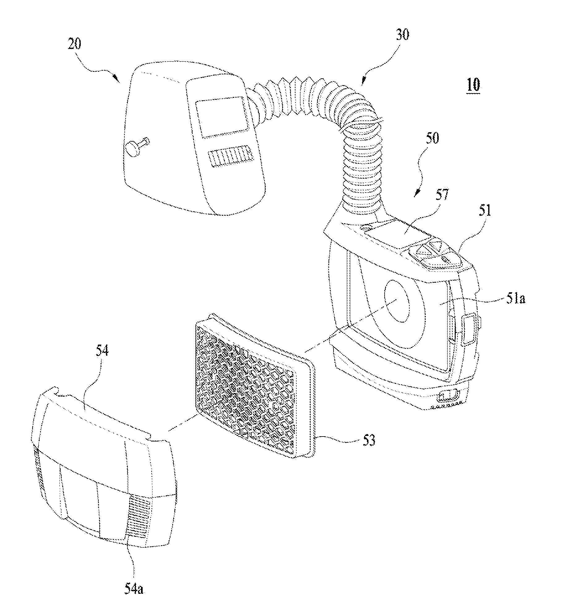
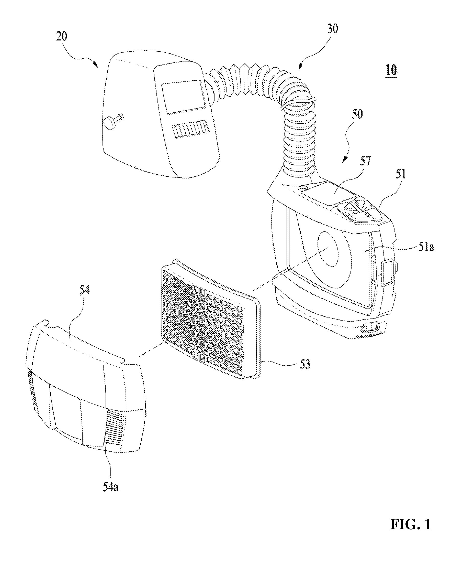
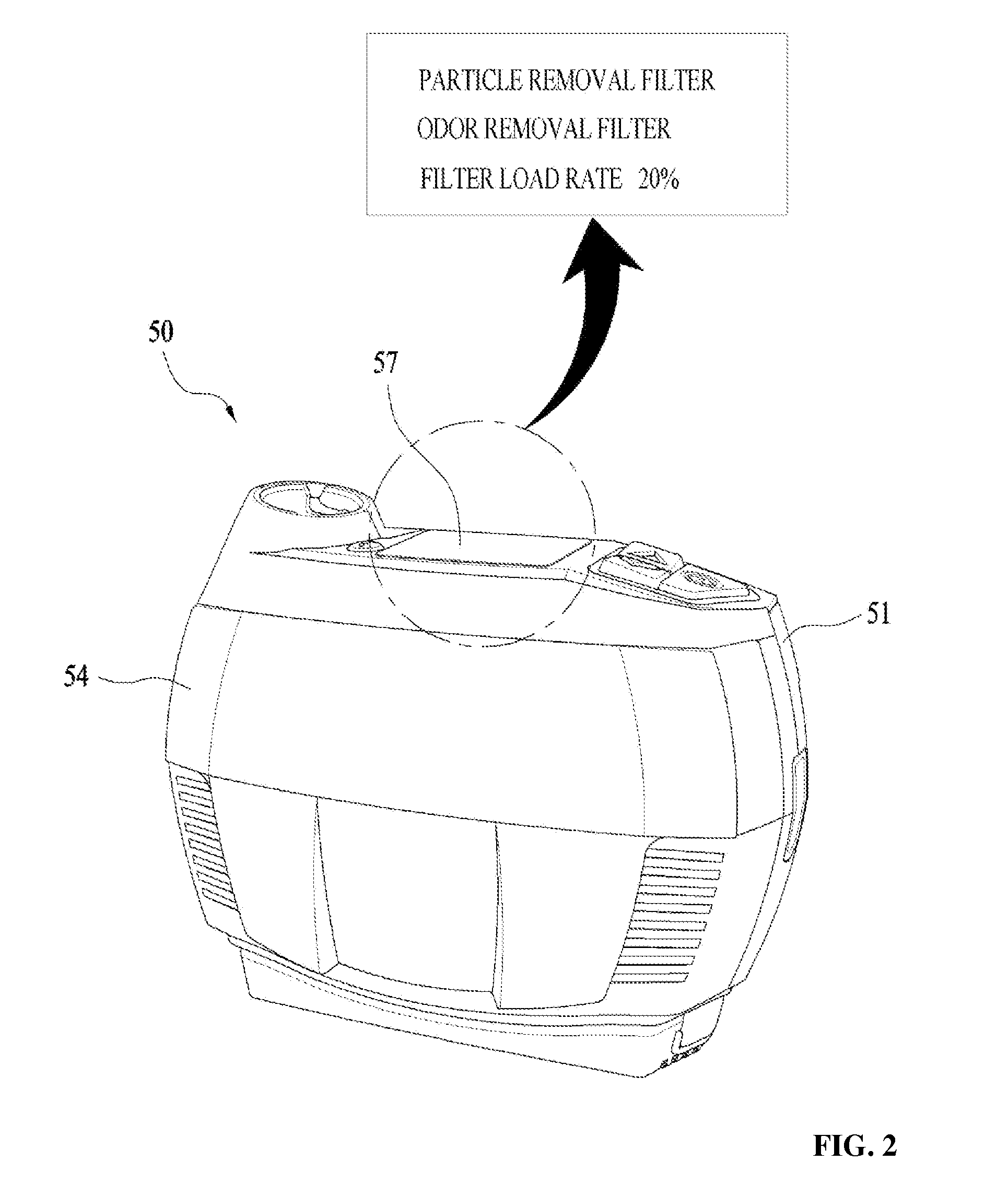
[0051]FIG. 3 schematically illustrates a state in which information on a particle removal filter 53a mounted in an air purifier 50 of a respirator 10 according to one embodiment of the present invention is recognized. FIG. 4 schematically illustrates a state in which information on an odor removal filter 53b mounted in the air purifier 50 of the respirator 10 according to one embodiment of the present invention is recognized. FIG. 5 is a flowchart of a method of recognizing information on the air purifier 50 of the respirator 10 according to one embodiment of the present invention.

[0052]Referring to FIGS. 1 a...


PUM


Abstract

Provided is a method of recognizing information on a filter unit mounted on an air purifier of a respirator wherein the air purifier and the filter unit of the respirator which filters polluted external air and supplies purified air to a worker are wirelessly interconnected such that a control unit of the air purifier may provide the worker with information on the filter unit such as a type, a load rate depending on a blockage degree of the filter unit, a final operation time, a residual operation time, and a replacement time of the filter unit through information data transmitted from the filter unit. It is possible to precisely recognize the filter unit appropriate for a workplace and a work environment, thereby preventing an error, failure, and malfunction of the filter unit and simultaneously with continuously working. The air purifier and the filter unit are wirelessly interconnected through radio frequency identification (RFID), wireless fidelity (Wi-Fi), near field communication (NFC), Bluetooth, or Zigbee to detect a type of a filter, recognize information of the detected filter such as an operation time and life thereof by counting an operation time of the filter, and allow a wearer to recognize the information.

Description

CROSS-REFERENCE TO RELATED APPLICATION[0001]This application claims priority to and the benefit of Korean Patent Application No. 2014-0082490, filed on Jul. 2, 2014, the disclosure of which is incorporated herein by reference in its entirety.BACKGROUND[0002]1. Field of the Invention[0003]The present invention relates to an air purifier of a respirator, and more particularly, to a structure and method for recognizing information on a filter unit installed in an air purifier of a respirator which filters polluted external air and supplies purified air to a worker who works in an extreme environment, in which the air purifier is wirelessly connected to the filter unit to provide the worker with information such as a type, operation time, and replacement time of the filter unit.[0004]2. Discussion of Related Art[0005]Generally, respirators applied to hard hats, used while welding, applied to face shields, and used against asbestos are products used in various industrial fields in extrem...

Claims


Application Information

Patent Timeline
Patent Type & Authority Applications(United States)
IPC IPC(8): A62B9/00A62B7/10A62B18/02
CPCA62B9/006A62B7/10A62B18/02
Inventor HUH, MOON-YOUNG
Owner OTOS WING
Why Eureka
Try Eureka