Blow molding device for a rotary bottle blowing machine and a method for using the same

a bottle blowing machine and blow molding technology, which is applied in the field of blow molding devices, can solve the problems of difficult assembly, high cost, and difficult control of structural accuracy, and achieve the effects of improving driving efficiency, reducing structure and cost of drive sources, and precise and stable driving movement through grooves

Active Publication Date: 2016-01-07
CHUM POWER MASCH CORP
View PDF0 Cites 15 Cited by
  • Summary
  • Abstract
  • Description
  • Claims
  • Application Information

AI Technical Summary

Benefits of technology

[0019]The present invention just needs one drive source M to move the respective components to carry out the step of mold opening or closing, the step of mold lifting, and the step of mold locking. The operation of mold opening and locking can be quickly carried out with only one-time input of drive power. Hence, the structure and cost of the drive source are simplified and reduced. The drive source...

Problems solved by technology

The requirements on the structural accuracy and quality are very strict and difficult to control, therefore, the device for blow molding containers as disclosed in U.S. Pat. No. 8,100,688 is difficult to assemble, high cost, and the structural accuracy is difficult to control.
To move the movable mold portion 26 and the base mold portion 23, it has to use a drive source to move the base mold portion 23 up and down, and another drive source to rotate the first drive shaft 24, therefore, the structure of the device of U.S. Pat. Application No. 20120177771A1 is too complicated and high cost.
However, in addition to the disadvantages of com...

Method used


Image

  • Blow molding device for a rotary bottle blowing machine and a method for using the same
  • Blow molding device for a rotary bottle blowing machine and a method for using the same
  • Blow molding device for a rotary bottle blowing machine and a method for using the same

Examples


Embodiment Construction

[0038]The present invention will be clearer from the following description when viewed together with the accompanying drawings, which show, for purpose of illustrations only, the preferred embodiment in accordance with the present invention.

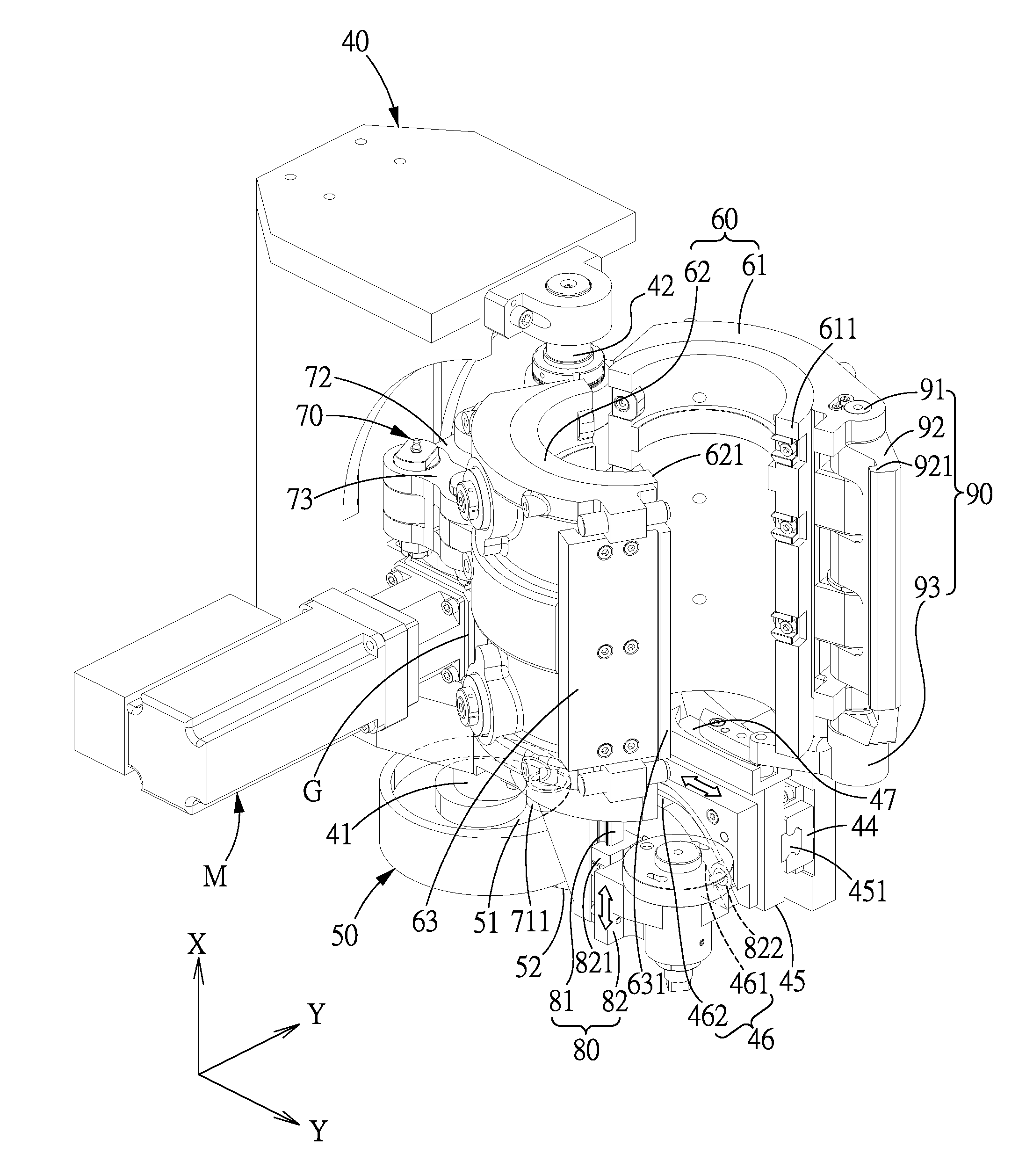
[0039]Referring to FIGS. 7-17, a blow molding device for a rotary bottle blowing machine in accordance with a preferred embodiment of the present invention comprises: a support base 40, a drive member 50, a mold assembly 60, an open / close control unit 70, a bottom mold unit 80, and a mold locking unit 90.

[0040]The support base 40 includes a power-input shaft 41, a mold-insert pivot 42 and a mold-insert control shaft 43 which extend along an axial direction X, and a direction perpendicular to the axial direction X is defined as a radial direction Y. The power-input shaft 41 is connected to and rotated by a drive source M. In this embodiment, the drive source M drives the power-input shaft 41 to rotate via a gearbox and the drive source M is a serv...


PUM

PropertyMeasurementUnit
Heightaaaaaaaaaa

Abstract

A blow molding device for a rotary bottle blowing machine includes: a support base including a power-input shaft and a mold-insert control shaft which are pivotally disposed on the support base and extend along an axial direction; a drive source for driving the power-input shaft and the mold-insert control shaft to rotate; and a mold assembly with a first and second movable mold inserts pivotally disposed on the support base. The mold assembly makes the first and second movable mold inserts pivot toward or away from each other, rotation of the power-input shaft makes a bottom mold unit move in the axial direction, and can lock the first and second movable mold inserts. A method for using the blow molding device includes steps of mold opening or closing, mold lifting, and mold locking, and these steps are performed by using a single drive source.

Description

BACKGROUND OF THE INVENTION[0001]1. Field of the Invention[0002]The present invention relates to a blow molding device, and more particularly to a blow molding device for a rotary bottle blowing machine and a method for using the same.[0003]2. Description of the Prior Art[0004]FIGS. 1 and 2 show a device for blow molding containers, which is disclosed in U.S. Pat. No. 8,100,688, wherein the blow molding station 10 essentially comprises a drive shaft 12 rotatably disposed on a support structure 11. On the support structure 11 are further fixed a stationary mold portion 13 and a movable mold portion 14 capable of pivoting with respect to the stationary mold portion 13. At the bottom of the stationary mold portion 13 is formed a cam track 131. The drive shaft 12 is connected to the movable mold portion 14 by a first connecting member 15 which is perpendicular to the drive shaft 12, and is connected to a base mold portion 17 via a second connecting member 16 which is located in a direct...

Claims


Application Information

Patent Timeline
IPC IPC(8): B29C49/42B29C49/36
CPCB29C49/4236B29L2031/712B29C49/36B29C49/56B29C2049/4892B29C2049/566
Inventor YANG, WEN-YUNGLAI, PO-CHENGNGUYEN, XUAN-QUYENLUO, ZHI-ZHONGZHANG, JIN-GEPAN, HUAI-RONGXIE, SHU-LIN
Owner CHUM POWER MASCH CORP
Why Eureka
Try Eureka