Acoustophoretic device with uniform fluid flow

a technology of acoustophoretic devices and fluids, which is applied in the direction of mechanical vibration separation, separation processes, chemistry apparatuses and processes, etc., can solve the problems of vertical flow path reducing velocity non-uniformities, reduce velocity non-uniformities, and improve separation of particles/secondary fluids , the effect of reducing velocity non-uniformities

Active Publication Date: 2016-01-07
FLODESIGN SONICS
View PDF3 Cites 9 Cited by
  • Summary
  • Abstract
  • Description
  • Claims
  • Application Information

AI Technical Summary

Benefits of technology

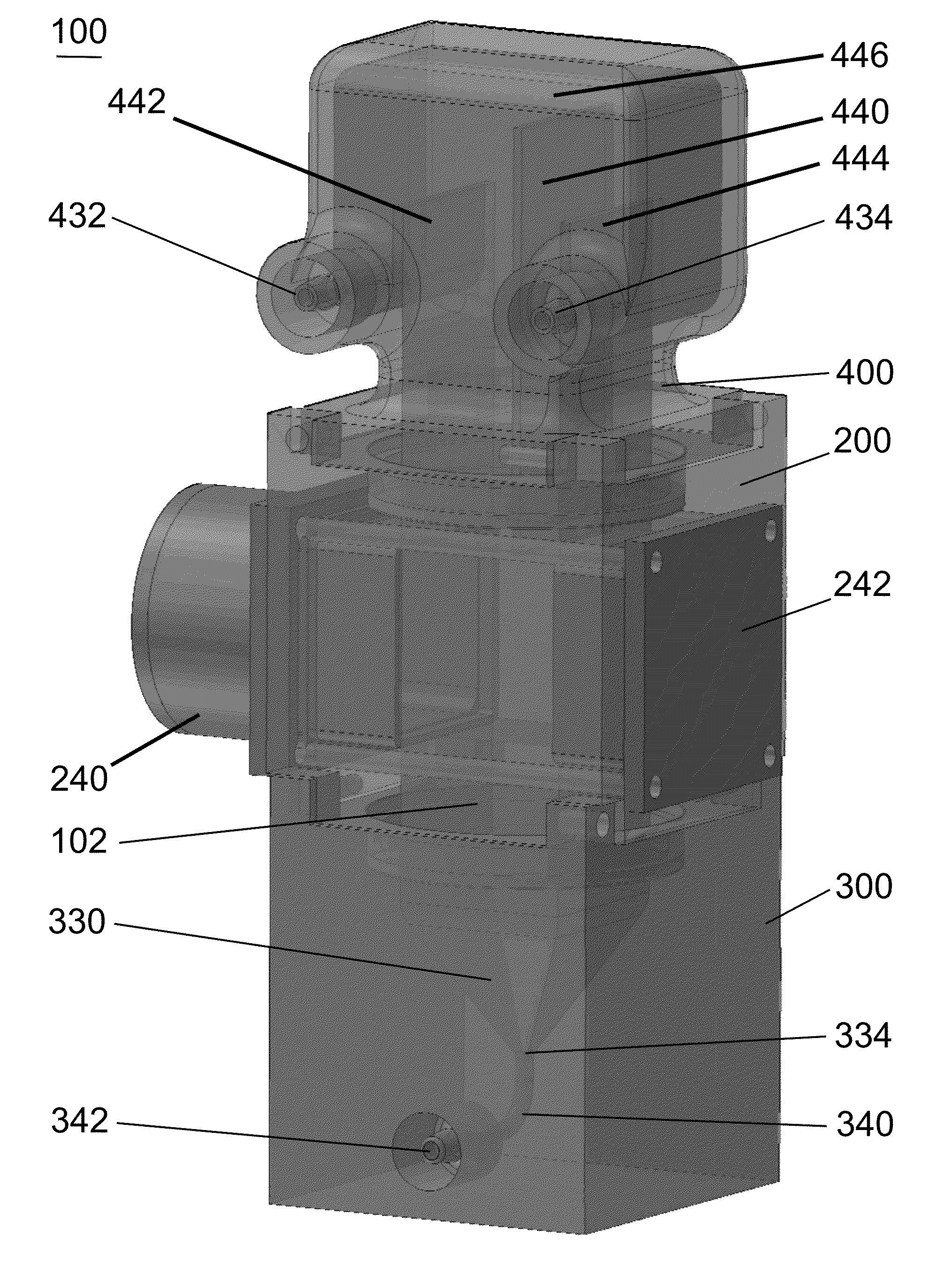
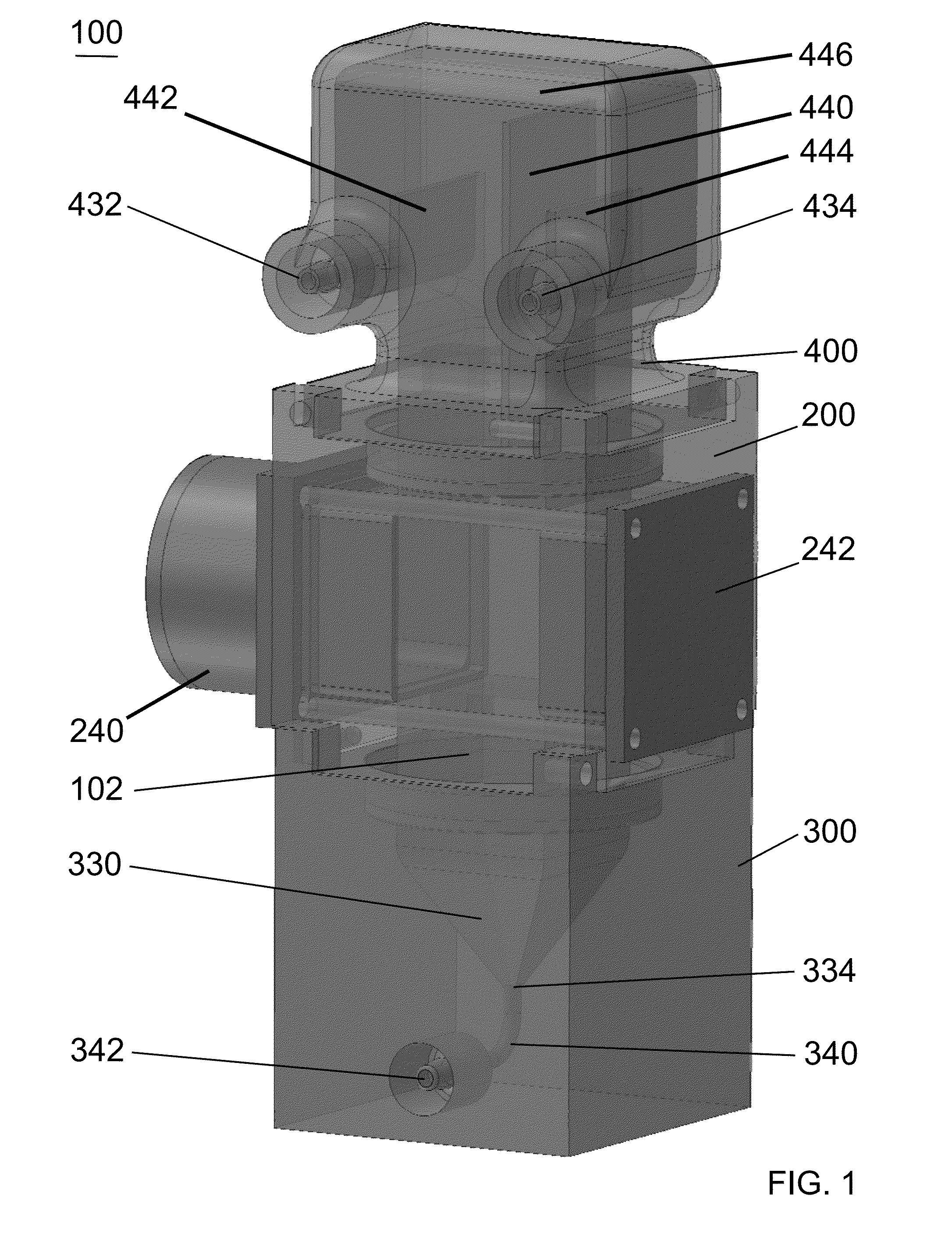
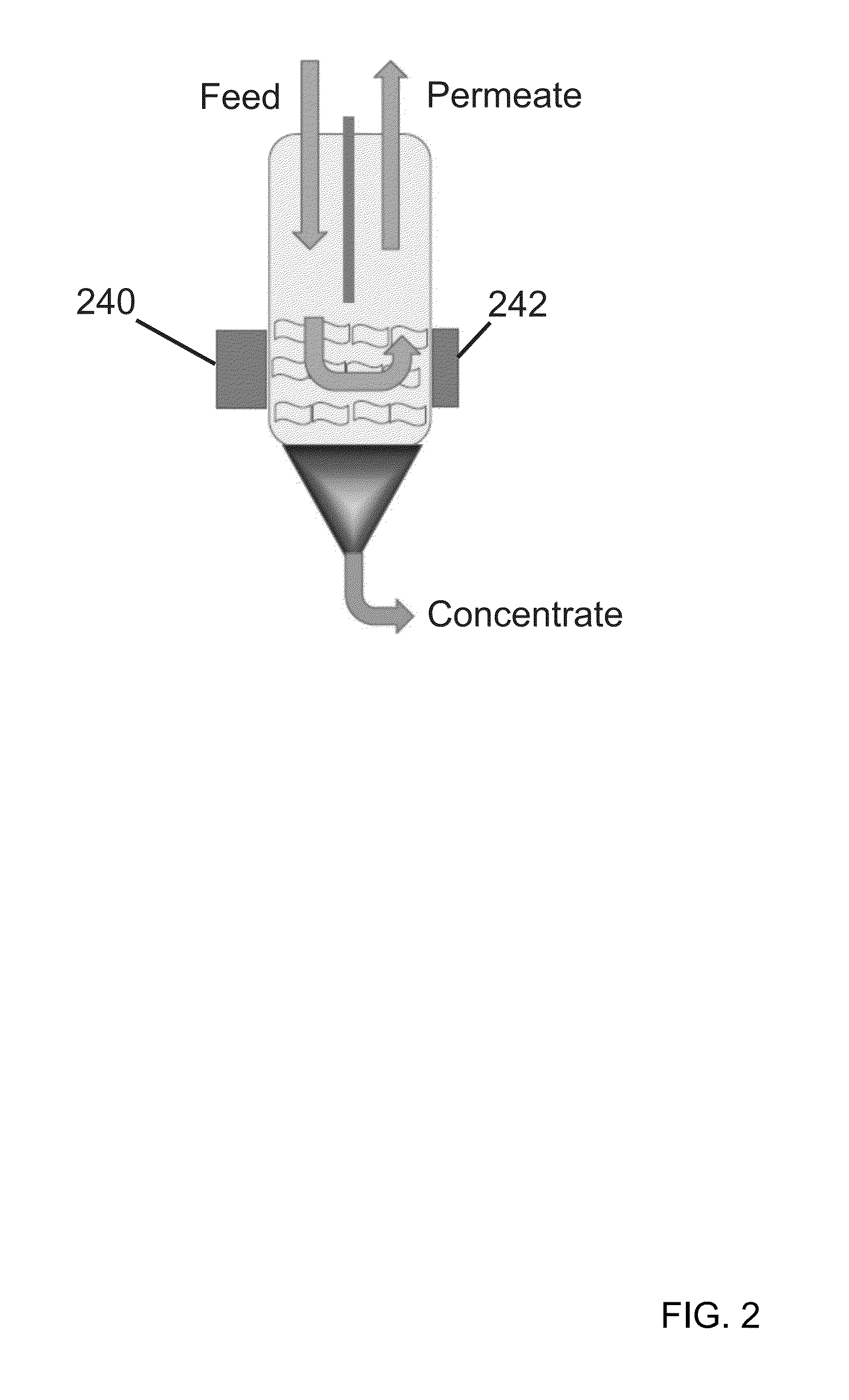
[0007]Briefly, the systems described herein all include a substantially vertical flow path of the mixture through the acoustic chamber in order to improve separation of particles/secondary fluid from a primary fluid using fluid dynamics. The vertical flow path reduces velocity non-uniformities in the acoustic chamber resultin

Problems solved by technology

The vertical flow path reduces velocity non-uniformitie

Method used


Image

  • Acoustophoretic device with uniform fluid flow
  • Acoustophoretic device with uniform fluid flow
  • Acoustophoretic device with uniform fluid flow

Examples


examples

[0136]Three different devices were made and tested for their cell separation efficiency. The baseline device was similar to FIG. 20, having a single dump diffuser on one side. Second, a device similar to FIG. 17 was used, having two dump diffusers and a shallow wall at an angle of 30 degrees (abbreviated 2DD30). Third, a device similar to FIG. 17 was used, having two dump diffusers and a shallow wall at an angle of 45 degrees (abbreviated 2DD45).

[0137]The devices were tested using a 1.5 volume % yeast solution. Each device used two transducers (arranged vertically one on top of the other) with 50 volts to the top transducer and 60 volts to the bottom transducer, operating at a transducer frequency 2.23 MHz. The flowthrough rate was about 270 mL / min, with about 8.1 mL / min concentrate drawoff. The cell separation efficiency was measured as the percentage reduction in turbidity between the feed and the permeate. Table 1 below provides the results:

TABLE 1Device% ClarificationBaseline902...


PUM

PropertyMeasurementUnit
Fractionaaaaaaaaaa
Fractionaaaaaaaaaa
Angleaaaaaaaaaa

Abstract

An acoustophoresis device which includes a substantially vertical flow path of the fluid mixture in order to improve separation of particles/secondary fluid from a primary fluid is disclosed. The vertical flow path reduces velocity non-uniformities in the acoustic chamber resulting from gravity forces. The device includes an acoustic chamber in which multidimensional acoustic standing waves are generated. The fluid can be introduced into the acoustic chamber using a dump diffuser in which a plurality of inlets enter near the bottom of the acoustic chamber such that flow symmetry reduces both, gravity driven flow non-uniformities, and any flow interference effects between inlet mixture flow into the acoustic chamber and the continuous gravity driven particle cluster drop out.

Description

CROSS-REFERENCE TO RELATED APPLICATIONS[0001]This application claims priority to U.S. Provisional Patent Application Ser. No. 62 / 020,088, filed on Jul. 2, 2014, and to U.S. Provisional Patent Application Ser. No. 62 / 154,672, filed on Apr. 29, 2015, the disclosures of which are hereby fully incorporated by reference in its entirety.BACKGROUND[0002]The ability to separate a particle / fluid mixture into its separate components is desirable in many applications. Physical size exclusion filters can be used for this purpose, where the particles are trapped on the filter and the fluid flows through the filter. Examples of physical filters include those that operate by tangential flow filtration, depth flow filtration, hollow fiber filtration, and centrifugation. However, physical filters can be complicated to work with. As the filter fills up, filtration capacity is reduced. Also, using such filters requires periodic stopping to remove the filter and obtain or clear the particles trapped th...

Claims


Application Information

Patent Timeline
IPC IPC(8): C02F1/36
CPCC02F1/36B01D21/0045B01D21/283
Inventor LIPKENS, BARTMCCARTHY, BRIANBARNES, JASONMEALEY, DANEROSS-JOHNSRUD, BENPRESZ, JR., WALTER M.CHITALE, KEDAR
Owner FLODESIGN SONICS
Why Eureka
Try Eureka