
Lightsheet microscopy with rotational-shear interferometry

Inactive Publication Date: 2016-01-07
WAYNE LEONARD RODENHAUSEN
View PDF5 Cites 5 Cited by
  • Summary
  • Abstract
  • Description
  • Claims
  • Application Information

AI Technical Summary

Benefits of technology

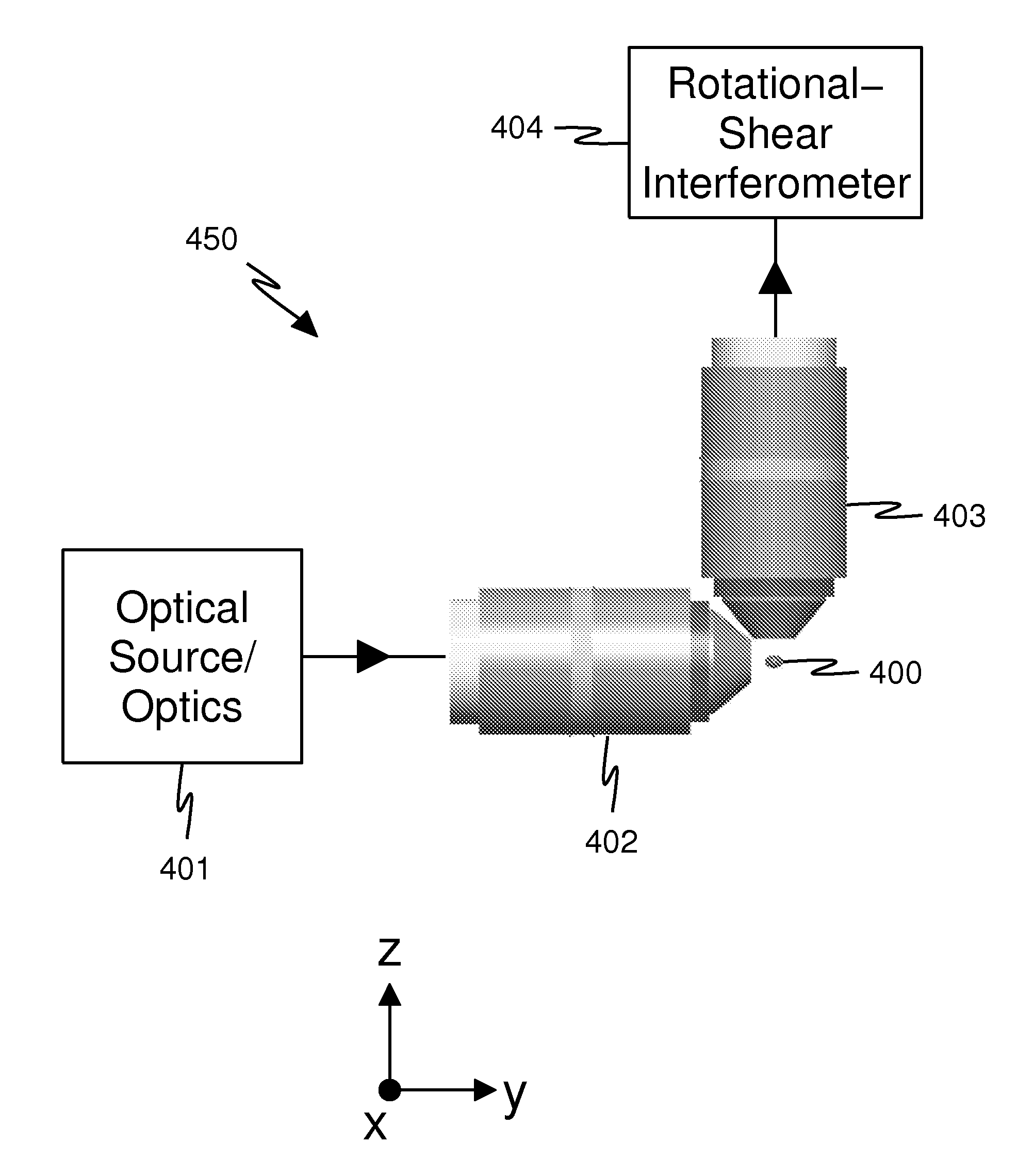
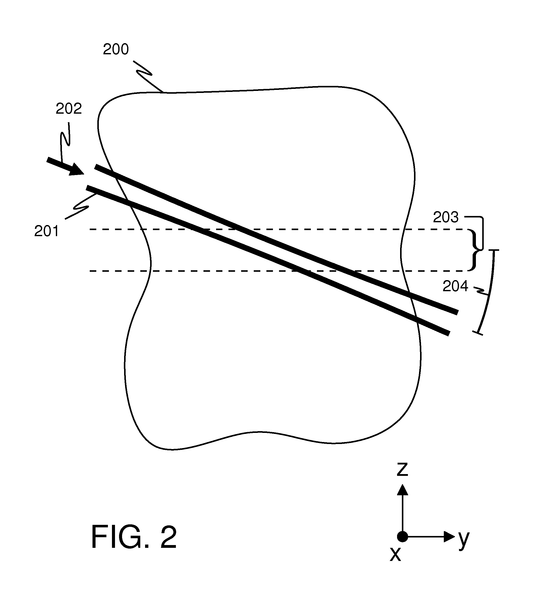
The present invention provides a RSI lightsheet microscope that combines lightsheet illumination and rotational-shear interferometry. This microscope has several technical effects, including improved image quality, reduced blurring, and improved depth of field. The microscope uses a detection microscope with a rotational-shear interferometer, which allows for the recording of data that can be processed to infer an image. The microscope is also designed to have a specific tilt-offset and z-offset, which can be adjusted to minimize image quality degradation. Overall, the RSI lightsheet microscope provides a better and more complete view of the microscopic world.

Problems solved by technology

Without the alignment the 2-D images recorded by the detection microscope will be blurred, and blurring is undesirable.
Significant effort and cost are needed to meet the alignment requirement.
The need for exacting z-alignment and tilt-alignment can complicate the design, manufacture, and / or use of many current lightsheet microscopes.
These constraints impede the system design.
Further, the system designer may be pushed harder to make tradeoffs against other system parameters and thus reduce overall system performance.
A decrease in the numerical aperture of a microscope degrades the lateral spatial resolution of the microscope, which is undesirable.
This complexity may increase system cost and may impede the system designer.
Furthermore, the exacting alignment requirements make system manufacture more difficult and more expensive.
More effort may be required to achieve the alignment requirements.
And greater cost may be required since the construction material choices are constrained and since more system complexity may be required.
Even after the system is manufactured, the exacting alignment requirements may negatively impact the use of the system in the field.
More effort may be required if the alignment is more exacting.
Related to this is a difficulty with many current lightsheet microscopes described by Huisken in U.S. patent application publication 2011 / 0115895, the entire contents of which application are incorporated herein by reference: typically, “the [lightsheet] is aligned before the experiment to illuminate the focal plane of the detection lens.
Refraction at the medium-sample interface will divert the [lightsheet] away from the focal plane and result in a blurry image.” This reduces the variety of samples that can be imaged without re-alignment.
The exacting nature of the alignment requirements may make this more difficult.
The difficulty is more acute for longer measurements since the alignment must be maintained for a longer time.
Another difficulty with many current lightsheet microscopes is the limitation on the lateral spatial resolution that can be achieved by the detection microscope.
The lateral spatial resolution of a conventional microscope is limited in a known way.
This is a limit to image quality.

Method used


Image

  • Lightsheet microscopy with rotational-shear interferometry
  • Lightsheet microscopy with rotational-shear interferometry
  • Lightsheet microscopy with rotational-shear interferometry

Examples


Embodiment Construction

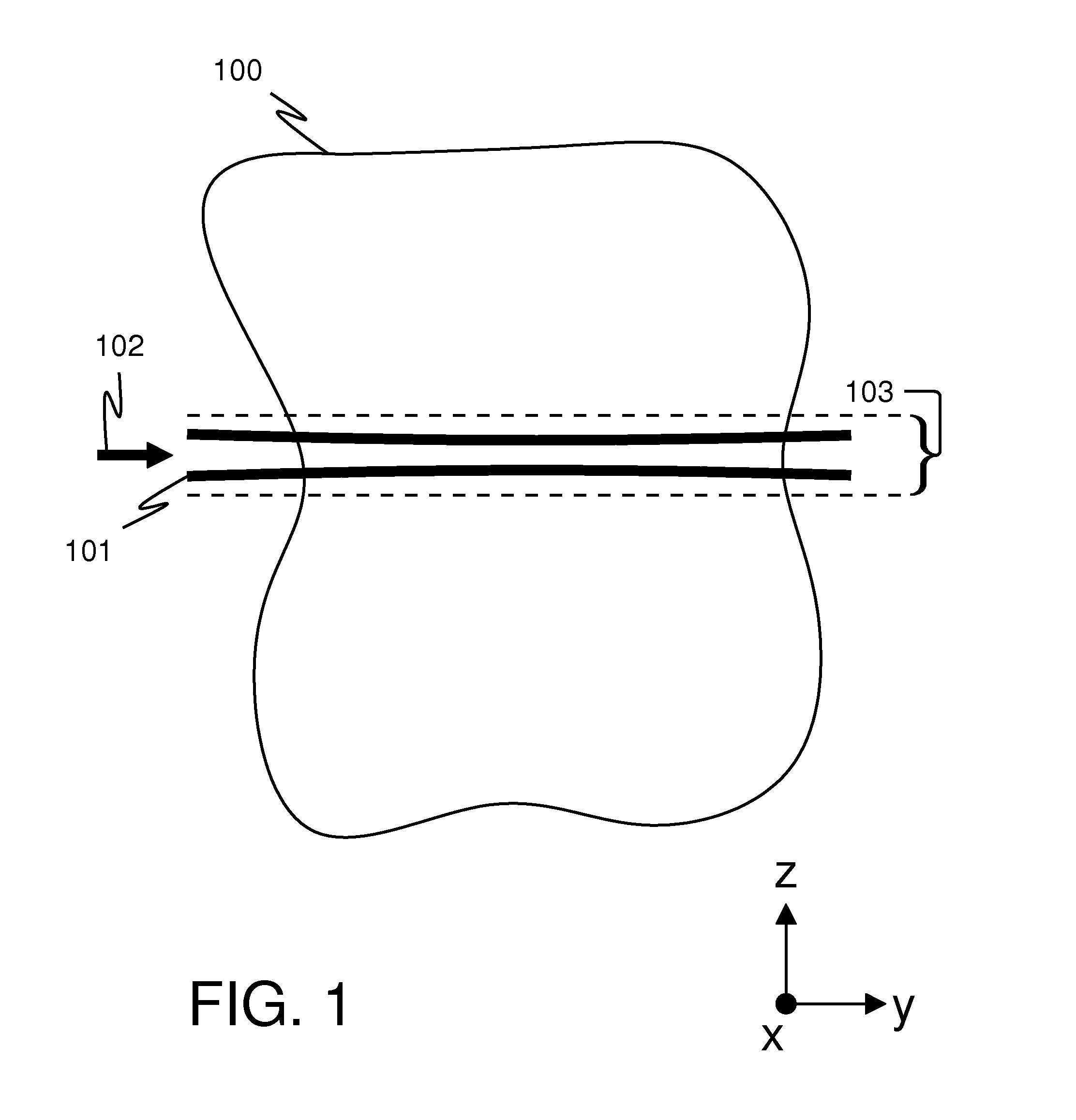
[0036]Turning now to the figures, FIG. 1 schematically illustrates the concept of lightsheet microscopy. FIG. 1 illustrates part of a lightsheet microscope representing a snapshot at one scan step of a sample 100 under study. Sample 100 could be a biological specimen, for example. Sample 100 is three-dimensional and extends in the “+ / −x”, “+ / −y”, and “+ / −z” directions. (Mutually orthogonal coordinate axes indicate the “x”, “y”, and “z” directions, with each arrow on each coordinate axis pointing in the positive direction along the axis. For example, the “+y” direction is to the right on the page.) For simplicity of illustration, only a two-dimensional slice of sample 100 is drawn.

[0037]Lightsheet 101 enters sample 100 in the direction indicated by arrow 102 and represented by a pair of thick lines. The lightsheet 101 is parallel to the x-y plane and has a slight curvature, customary of the behavior of a Gaussian beam. A Gaussian beam is one form of illumination used to generate a li...


PUM


Abstract

Devices and methods for lightsheet microscopy using rotational-shear interferometry are provided. Advantages include improved lateral spatial resolution and easier alignment.

Description

FIELD OF THE INVENTION[0001]The present invention relates generally to lightsheet microscopy, and more particularly but not exclusively to rotational-shear-interferometer lightsheet microscopes.BACKGROUND OF THE INVENTIONLightsheet Microscopy[0002]Lightsheet microscopy is a technique for imaging a sample in all three spatial dimensions (“3-D”), in which a “sheet” of light illuminates one slice at a time of the sample under study. This is illustrated in FIG. 1. (Lightsheet microscopy is sometimes also referred to as “selective plane illumination microscopy.”) A “detection microscope” records a two-dimensional (“2-D”) image of the region illuminated by the lightsheet. The lightsheet may be scanned step-by-step through the sample, or the sample may be scanned step-by-step through the lightsheet. A 2-D image is recorded at each step. Eventually the entire object may be illuminated and imaged, and the 2-D images fused together with software to make a 3-D image of the sample.[0003]The 3-D...

Claims


Application Information

Patent Timeline
IPC IPC(8): G01B9/02G02B21/00G02B21/36
CPCG02B21/0056G01B9/0203G02B21/006G02B21/367G02B21/0032G02B3/06G02B21/247
Inventor WAYNE, LEONARD, RODENHAUSEN
Owner WAYNE LEONARD RODENHAUSEN
Learn More