Portable charging device

a charging device and portability technology, applied in the direction of transportation and packaging, sustainable buildings, safety/protection circuits, etc., can solve the problems of many consumers not having the luxury of long time, slow recharging, and many people's built-in batteries are often too small to accommodate everyday use, etc., to achieve fast recharging, high power output, and convenient use.

Inactive Publication Date: 2016-01-07
ZETTALY INC
View PDF4 Cites 13 Cited by
  • Summary
  • Abstract
  • Description
  • Claims
  • Application Information

AI Technical Summary

Benefits of technology

[0016]Compared to known types of rechargeable battery packs in the prior art, the new portable charging device provides better convenience by using commonplace computer AC / DC power adapter as the input and achieves faster recharging at comparable size, weight, and capacity by serially connecting multiple battery cells to take advantage of the computer power adapter's high power output. At 10,000 mAh capacity, for example, the new portable charging device can shorten required full recharge time by more than 2 hours.

Problems solved by technology

With increasing usage of mobile devices such as smartphones, tablets, and cameras, people often find the capacities of their devices' built-in batteries too small to accommodate everyday use.
Current high-capacity battery packs on the market come in a variety of sizes and capacities that suit consumer needs, but they are slow at recharging themselves, e.g., taking 4-12 hours to charge 10,000 mAh.
That's a very long time that many consumers don't have the luxury for, especially when they are traveling or moving from place to place in everyday life with their mobile devices low on power.
Some battery packs use large AD / DC adapter either built in or in standalone to speed up the charging, but result in very bulky devices that are no longer suited for portable use.

Method used


Image

  • Portable charging device
  • Portable charging device
  • Portable charging device

Examples


Embodiment Construction

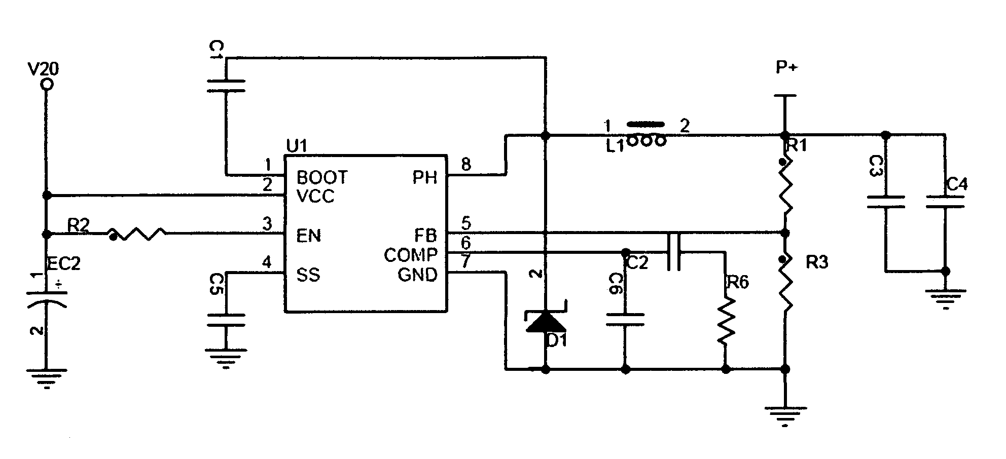
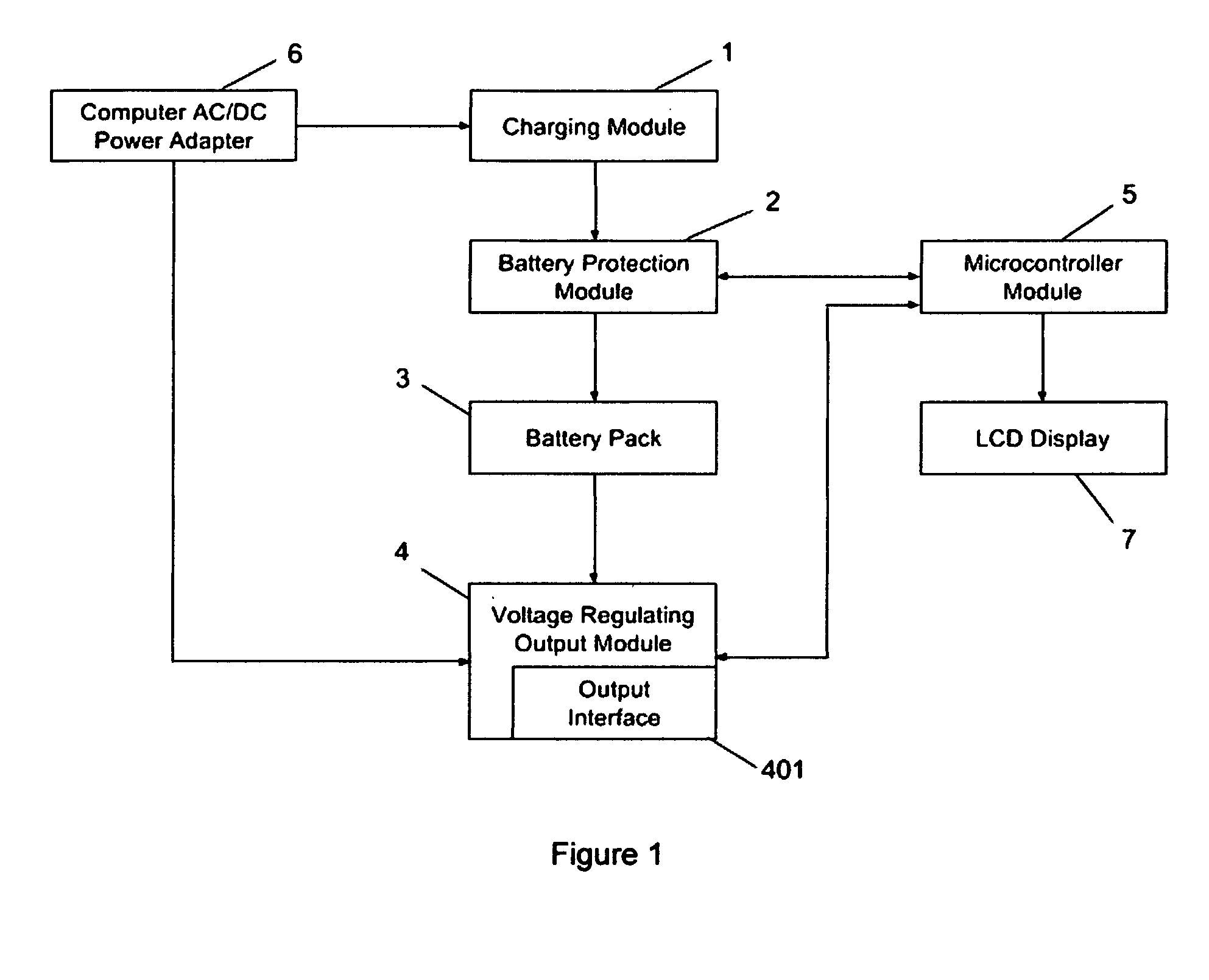
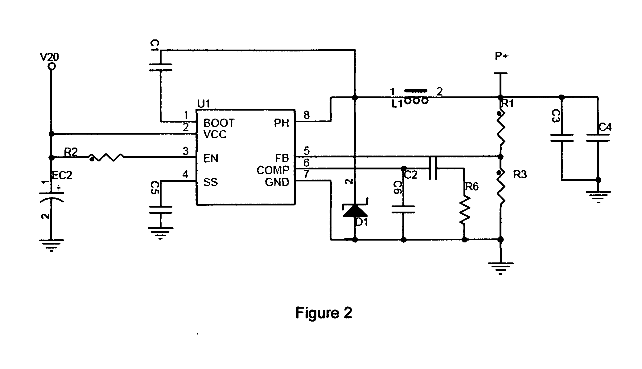
[0026]Turning now descriptively to the drawings of the embodiment of the utility model, in which similar reference characters denote similar elements throughout the several views, FIG. 1 through 9 illustrate a portable charging device (FIG. 1) that includes a charging module (FIG. 2), a battery protection module (FIG. 3), a built-in battery pack with multiple battery cells (FIG. 4), a voltage regulating output module (FIG. 8-9), a microcontroller module (FIG. 5), and an LCD display (FIG. 6-7). Said charging device 1 powers its externally connected electronic devices and in turn charges their batteries. Said charging module uses an input interface that matches the output interface of a personal computer's AC / DC power adapter. Said charging module charges said built-in battery pack through said battery protection module. Said built-in battery pack is connected to said voltage regulating output module to power externally connected electronic devices. Said microcontroller module connect...


PUM


Abstract

The present utility model discloses a portable charging device that includes a charging module, a battery protection module, a built-in battery pack with multiple battery cells, a voltage regulating output module, a microcontroller module, and an LCD display. Said charging device powers its externally connected electronic devices and in turn charges the batteries of those devices. Said charging module uses an input interface that matches the output interface of a personal computer's AC/DC power adapter. Said charging module charges said built-in battery pack through said battery protection module. Said built-in battery pack are connected to said voltage regulating output module to power externally connected electronic devices. Said microcontroller module connects to said battery protection module and said voltage regulating output module to control the charging and discharging process of said portable charging device. Said portable charging device provides convenience to its user by reusing the user's existing computer AC/DC power adapter as the energy input. It packs multiple battery cells and connects them electronically in series to maximize the energy intake from the computer AC/DC power adapter, improve charging efficiency, and significantly shorten the charging time of said charging device.

Description

BACKGROUND OF THE INVENTION[0001]1. Field of the Invention[0002]The present invention relates generally to portable charging device and more specifically it relates to portable rechargeable external battery packs also known as power banks that are used to power and charge consumer electronics such as smartphones, tablets, cameras.[0003]2. Description of the Prior Art[0004]With increasing usage of mobile devices such as smartphones, tablets, and cameras, people often find the capacities of their devices' built-in batteries too small to accommodate everyday use. As a result, a growing number of consumers start carrying with them large-capacity external battery packs (a.k.a. power banks) that can power and charge their mobile devices when needed.[0005]Current high-capacity battery packs on the market come in a variety of sizes and capacities that suit consumer needs, but they are slow at recharging themselves, e.g., taking 4-12 hours to charge 10,000 mAh. That's a very long time that m...

Claims


Application Information

Patent Timeline
Patent Type & Authority Applications(United States)
IPC IPC(8): H02J7/00
CPCH02J7/0052H02J7/007H02J7/0026H02J7/0014H02J7/00034H02J7/0029H02J7/00Y02B40/00
Inventor LIU, DAKE
Owner ZETTALY INC
Why Eureka
Try Eureka