Method of Manufacturing Wound Stator for Alternating-Current Generator

a technology of alternating-current generator and wound stator, which is applied in the manufacture of dynamo-electric machines, dynamo-electric machines, electrical equipment, etc., can solve the problems of reducing power generation efficiency, complex winding and folding, and disadvantages of conventional windings

Inactive Publication Date: 2016-01-07
VICTORY INDAL
View PDF3 Cites 4 Cited by
  • Summary
  • Abstract
  • Description
  • Claims
  • Application Information

AI Technical Summary

Problems solved by technology

To achieve high power generation, a large number of coils are used, and thus the winding and folding become complex.
However, the conventional windings have disadvantages.
These air gaps result in an undesirable increase of magnetic resistance which lowers power generation efficacy.
In addition, since the stator ring is large, the corresponding rotor also has to be large so that the two can fit each other, which increases the size of the generator that comprises them.
A large generator will limit the usable space of a vehicle.
For example, in a stator ring having 96 grooves in which each groove has two wire units, after wire insertion is completed, there are a total of 384 wire ends and 192 solder joints, and the process for manufacturing such stator may be complex.
In addition, the flat copper wire used in such stator may be more expensive than a round copper wire.

Method used


Image

  • Method of Manufacturing Wound Stator for Alternating-Current Generator
  • Method of Manufacturing Wound Stator for Alternating-Current Generator
  • Method of Manufacturing Wound Stator for Alternating-Current Generator

Examples


Embodiment Construction

[0032]The characteristics, subject matter, advantages, and effects of the present invention are detailed hereinafter by reference to embodiments of the present invention and the accompanying drawings. It is understood that the drawings referred to in the following description are intended only for purposes of illustration and do not necessarily show the actual proportion and precise arrangement of the embodiments. Therefore, the proportion and arrangement shown in the drawings should not be construed as limiting or restricting the scope of the present invention.

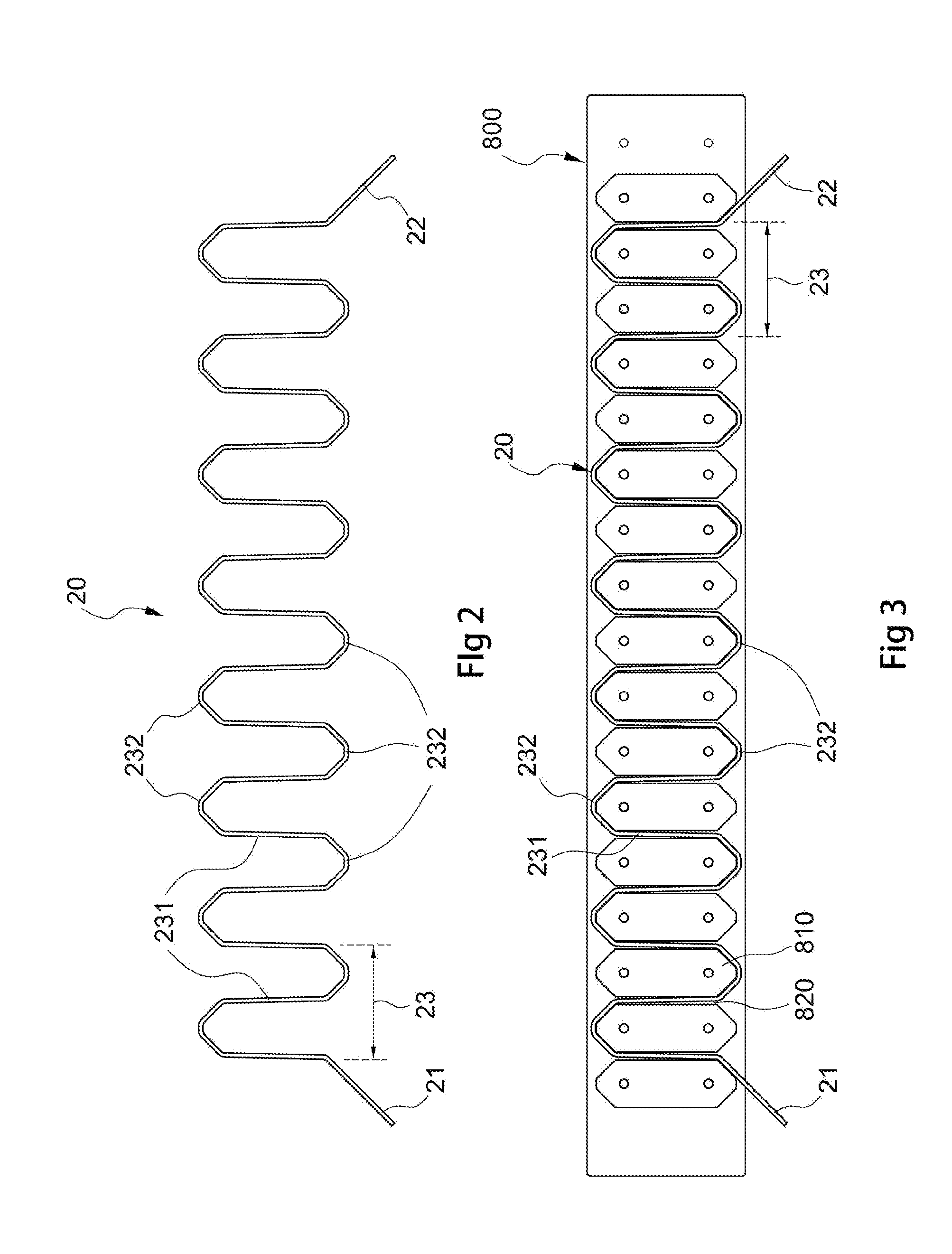
[0033]FIG. 2 is a schematic view of a wire for a stator of a vehicle alternating-current generator according to one embodiment of the present invention. As shown in FIG. 2, a wire 20 includes a first end 21, a second end 22, and a plurality of wave-shaped coils 23 located between the first end 21 and the second end 22, and each wave-shaped coil 23 is formed by a plurality of straight portions 231 and a plurality of curved por...


PUM


Abstract

The present invention relates to a method of manufacturing a wound stator. The method promises the following steps: (1) providing a stator, which has a plurality of radial grooves arranged at an inner circumference of the stator, (2) providing a plurality of wires for the stator, and (3) sequentially embedding the straight portions of each wire in corresponding grooves of the stator so that each of the grooves is embedded with the wires. Each of the plurality of wire comprises: a first end, a second end, and a plurality of wave-shaped coils located between the first end and second end. Each wave-shaped coil is formed of straight portions and curved portions that alternate with each other.

Description

CROSS-REFERENCE TO RELATED APPLICATIONS[0001]The present invention claims the benefit of priority of Taiwan application TW 103122780 of Jul. 1, 2014, entitled “Method of Manufacturing Wound Stator for Alternating-Current Generator,” the contents of which are herein incorporated by reference.BACKGROUND[0002]1. Field of the Invention[0003]The present invention relates to a method of manufacturing a wound stator, more particularly to a wound stator for a three-phase alternating-current generator.[0004]2. Description of Related Art[0005]An alternating-current generator is used for converting mechanical energy into alternating-current electric energy. In a vehicle alternating-current generator, the output power of an engine drives a rotor of the generator to rotate within a stator to convert mechanical energy of the engine into electric energy to charge a storage battery, which then supplies electric energy to electrical parts of a vehicle.[0006]A vehicle alternating-current generator ty...

Claims


Application Information

Patent Timeline
Patent Type & Authority Applications(United States)
IPC IPC(8): H02K15/04
CPCH02K15/0478H02K15/085H02K3/12H02K2213/03
Inventor WANG, CHUN-YUANLIOU, MING-LAANG
Owner VICTORY INDAL
Why Eureka
Try Eureka