Primer layer for plating process, laminate for circuit board and production method for same, and multilayer circuit board and production method for same

a plating process and circuit board technology, applied in the direction of synthetic resin layered products, vehicle sealing arrangements, animal housings, etc., can solve the problems of short circuit failure or open failure, insufficient response to achieve more fine wiring, and inability to manufacture multi-layer wiring boards in a good yield. , to achieve the effect of high heat resistance, high adhesiveness and high density of wiring

Inactive Publication Date: 2014-06-05
HITACHI CHEM CO LTD
View PDF7 Cites 3 Cited by
  • Summary
  • Abstract
  • Description
  • Claims
  • Application Information

AI Technical Summary

Benefits of technology

[0024]According to the present invention, a primer layer for plating process exhibiting high adhesiveness to an electroless copper plating and capable of coping with high density of wirings of semiconductor packages; a laminate for wiring board having the primer layer and a method for manufacture thereof; and a multilayer wiring board having the primer layer and a method for manufacture thereof can be provided.
[0025]Also, high solder heat resistance capable of coping with lead-free soldering can be exhibited.MODES FOR CARRYING OUT THE INVENTION[Primer Layer for Plating Process]
[0026]The primer layer for plating process of the present invention is formed of a resin composition for primer layer comprising (A) a polyfunctional epoxy resin (hereinafter also referred to as “component (A)”), (B) an epoxy resin curing agent (hereinafter also referred to as “component (B)”), and (C) a phenolic hydroxyl group-containing polybutadiene-modified polyamide resin having structural units represented by the following formulae (i), (ii) and (iii) (hereinafter also referred to as “component (C)”).
[0027]In the formulae, each of a, b, c, x, y, and z represents an average degree of polymerization; a represents an integer of from 2 to 10; b represents an integer of from 0 to 3; c represents an integer of from 3 to 30; when x is 1, then (y+z) represents an integer of from 2 to 300((y+z=x)); when y is 1, then z is 20 or more (z / y); each of R, R′, and R″ independently represents a divalent group derived from an aromatic diamine or an aliphatic diamine; and each R′″ independently represents a divalent group derived from an aromatic dicarboxylic acid, an aliphatic dicarboxylic acid, or an oligomer having a carboxyl group at both ends thereof.
[0028]Incidentally, specifically, R, R′, R″, and R′″ are derived from a diamine raw material and a dicarboxylic acid raw material as described later.
[0029]Also, a weight average molecular weight of the phenolic hydroxyl group-containing polybutadiene-modified polyamide resin (C) is preferably from 60,000 to 250,000, and more preferably from 80,000 to 200,000.

Problems solved by technology

But, such correspondence was insufficient for achieving more fine wiring because the copper foil to be removed is thick.
Under such a situation, according to the conventional methods of securing an adhesive force to the electroless copper plating by utilizing a large roughened shape obtained by roughening the surface (anchor effect), there is a concern that fine circuits of not more than 10 μm cause short circuit failure or open failure.
For that reason, multilayer wiring boards cannot be manufactured in a good yield.
On the other hand, if the roughened shape is made small, the adhesive force to the electroless copper plating is lowered, and a failure such as separation of a line is generated.
But, this insulating film does not aim to make the roughened shape of the surface smooth, so that it was not sufficient as a substrate for semiconductor package capable of coping with the wiring fineness in recent years.
On the other hand, following thinning of electronic components, the thickness of a wiring board to be used is becoming thin.
As a result, in the case where an insulating resin not containing a glass cloth is used as an insulating layer in place of the prepreg, there was a concern that a warp at the time of mounting becomes large, leading to a lowering of the connection reliability.
However, there are involved some problems to be solved, such as necessity of high-density wiring by the additive method.
But, since an adhesive layer is formed by coating an adhesive on the cured laminate, taking into consideration adhesiveness of an interface between the adhesive layer and the laminate, the adhesive layer is required to have a thickness of from 10 to 50 μm, and hence, this technology is not adapted for thinning.
But, in the case of subjecting a build-up substrate fabricated using this material to a peel test by bending at 90°, adhesiveness between the insulating material and copper was not sufficient.

Method used


Image

  • Primer layer for plating process, laminate for circuit board and production method for same, and multilayer circuit board and production method for same
  • Primer layer for plating process, laminate for circuit board and production method for same, and multilayer circuit board and production method for same
  • Primer layer for plating process, laminate for circuit board and production method for same, and multilayer circuit board and production method for same

Examples


preparation example 1

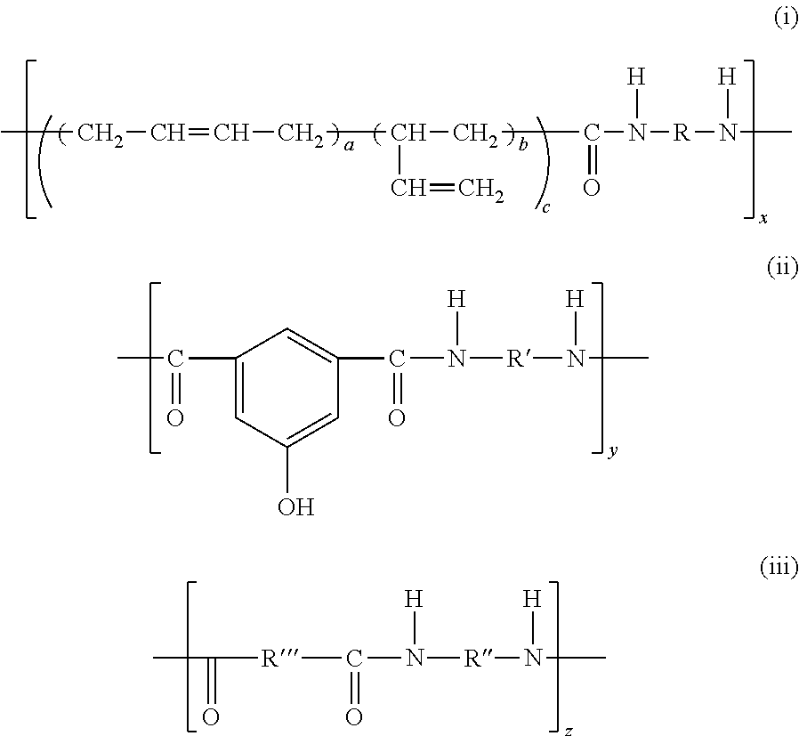
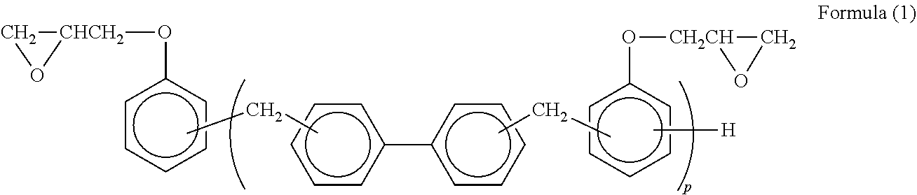
[0090]6.75 g of N,N-dimethylacetamide (DMAc) was blended with 0.75 g of a phenolic hydroxyl group-containing polybutadiene-modified polyamide (a trade name: BPAM-155, manufactured by Nippon Kayaku Co., Ltd.) as the component (C); 10 g of a biphenyl aralkyl type epoxy resin (a trade name: NC-3000H, manufactured by Nippon Kayaku Co., Ltd.) as the component (A), 4.1 g of a cresol novolak type phenol resin (a trade name: KA-1165, manufactured by DIC Corporation) as the component (B), and 0.1 g of 2-phenylimidazole (a trade name: 2PZ, manufactured by Shikoku Chemicals Corporation) as a curing accelerator were then added; and thereafter, the mixture was diluted with a mixed solvent consisting of DMAc and methyl ethyl ketone, thereby obtaining a resin varnish A for primer layer for plating process (solid content concentration: about 25% by mass).

preparation example 2

[0091]13.5 g of N,N-dimethylacetamide (DMAc) was blended with 1.5 g of a phenolic hydroxyl group-containing polybutadiene-modified polyamide (a trade name: BPAM-155, manufactured by Nippon Kayaku Co., Ltd.) as the component (C); 10 g of a biphenyl aralkyl type epoxy resin (a trade name: NC-3000H, manufactured by Nippon Kayaku Co., Ltd.) as the component (A), 3.6 g of a novolak type phenol resin (a trade name: TD-2090, manufactured by DIC Corporation) as the component (B), 0.1 g of 2-phenylimidazole (a trade name: 2PZ, manufactured by Shikoku Chemicals Corporation) as a curing accelerator, and 0.9 g of fumed silica (a trade name: R972, manufactured by Nippon Aerosil Co., Ltd.) were then added; and thereafter, the mixture was diluted with a mixed solvent consisting of DMAc and methyl ethyl ketone (solid content concentration: about 25% by mass). Thereafter, a uniform resin varnish B for primer layer for plating process was obtained using a disperser (a trade name: NANOMIZER, manufactu...

preparation example 3

[0092]A resin varnish C for primer layer for plating process (solid content concentration: about 25% by mass) was obtained in the same manner as that in Preparation Example 2, except that the epoxy resin curing agent as the component (B) was changed to bisphenol A novolak (a trade name: YLH129, manufactured by Mitsubishi Chemical Corporation), and the components were blended in an amount shown in Table 1.


PUM

PropertyMeasurementUnit
thicknessaaaaaaaaaa
average primary particle diameteraaaaaaaaaa
Raaaaaaaaaaa

Abstract

Disclosed are a primer layer for plating process exhibiting high adhesiveness to an electroless copper plating and capable of coping with high density of wirings of semiconductor packages; a laminate for wiring board having the primer layer and a method for manufacture thereof; and a multilayer wiring board having the primer layer and a method for manufacture thereof. Specifically disclosed are a primer layer for plating process formed of a resin composition for primer layer including (A) a polyfunctional epoxy resin, (B) an epoxy resin curing agent, and (C) a phenolic hydroxyl group-containing polybutadiene-modified polyamide resin having specified structural units, wherein a blending proportion of the component (C) is 5 parts by mass or more and less than 25 parts by mass based on 100 parts by mass of a total sum of the component (A) and the component (B); a laminate for wiring board having the primer layer and a method for manufacture thereof; and a multilayer wiring board having the primer layer and a method for manufacture thereof.

Description

FIELD OF THE INVENTION[0001]The present invention relates to a primer layer for plating process, a laminate for wiring board having the primer layer and a method for manufacture thereof, and a multilayer wiring board having the primer layer and a method for manufacture thereof.RELATED ART[0002]It was general that a multilayer wiring board is manufactured in the following method. That is, first of all, a material (prepreg) prepared by impregnating a glass cloth with an epoxy resin and forming in a semi-cured state is superimposed on an insulating substrate having an internal layer circuit formed on one surface or both surfaces thereof together with a copper foil, followed by lamination and integration by a heat press. Thereafter, a hole for interlayer connection, which is called a through-hole, is bored using a drill. An inner wall of the through-hole and a surface of the copper foil are subjected to electroless plating, and if desired, electroplating is further performed, thereby al...

Claims


Application Information

Patent Timeline
Patent Type & Authority Applications(United States)
IPC IPC(8): H05K1/03H05K3/00H05K1/02
CPCH05K1/0366H05K3/007H05K1/0298H05K1/0373H05K2201/0209H05K3/4676C23C18/1844C25D5/34C25D7/0614C23C18/1653C09D5/002C08L63/00Y10T156/1043Y10T428/249921C09D163/00C23C18/20H05K1/03H05K3/18
Inventor FUJIMOTO, DAISUKEYAMADA, KUNPEIOGAWA, NOBUYUKIMURAI, HIKARI
Owner HITACHI CHEM CO LTD
Why Eureka
Try Eureka