Contact imager

a contact imager and imager technology, applied in the field of contact imagers, can solve the problems of inability to obtain the results of a second or third exposure, not quantitative, distorted or difficult to view, etc., and achieve the effect of more accurate and sensitive signal detection

Active Publication Date: 2016-01-07
BIO RAD LAB INC
View PDF5 Cites 12 Cited by
  • Summary
  • Abstract
  • Description
  • Claims
  • Application Information

AI Technical Summary

Benefits of technology

[0004]The present disclosure provides apparatus and techniques that allow results to be obtained simultaneously on film and by digital scanner. This allows the user to obtain the film image for record keeping, while simultaneously learning quantitative information from the digital scan. The digital image can be viewed in real time, and signal strength monitored, so that the film can be developed at an appropriate time. Also provided are apparatus and techniques that allow results to be obtained simultaneously from two opposing digital scanners, which allows for more accurate and sensitive signal detection.

Problems solved by technology

Film results are not, however, quantitative.
When the assay relies on a chemiluminescent signal that decays with time, it might not be possible to obtain results from a second or third exposure.
In some cases however, the result can be distorted or difficult to view, e.g., because of pixel size.

Method used


Image

  • Contact imager
  • Contact imager
  • Contact imager

Examples


example 1

Configurations for Use of Single-Sensor Device

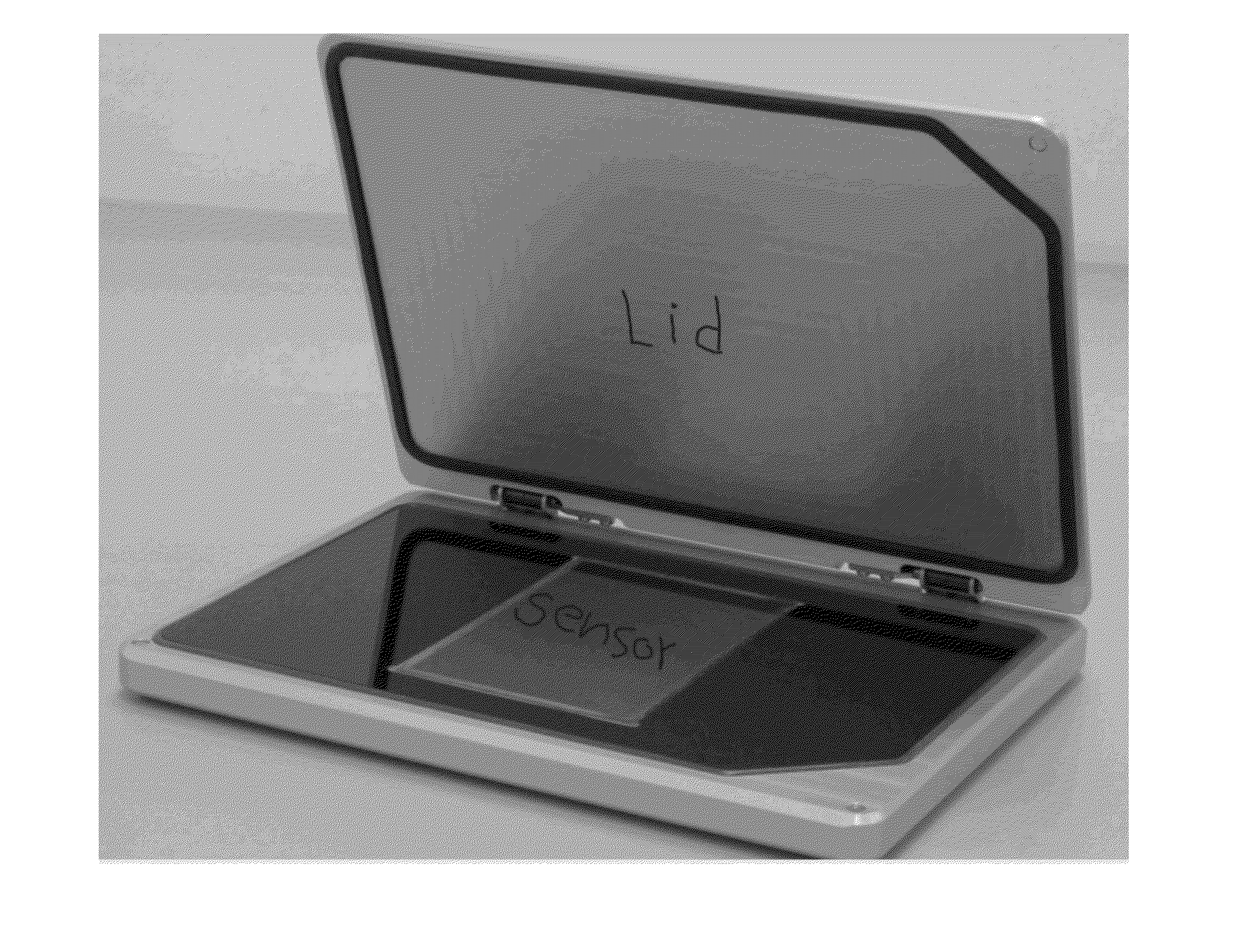
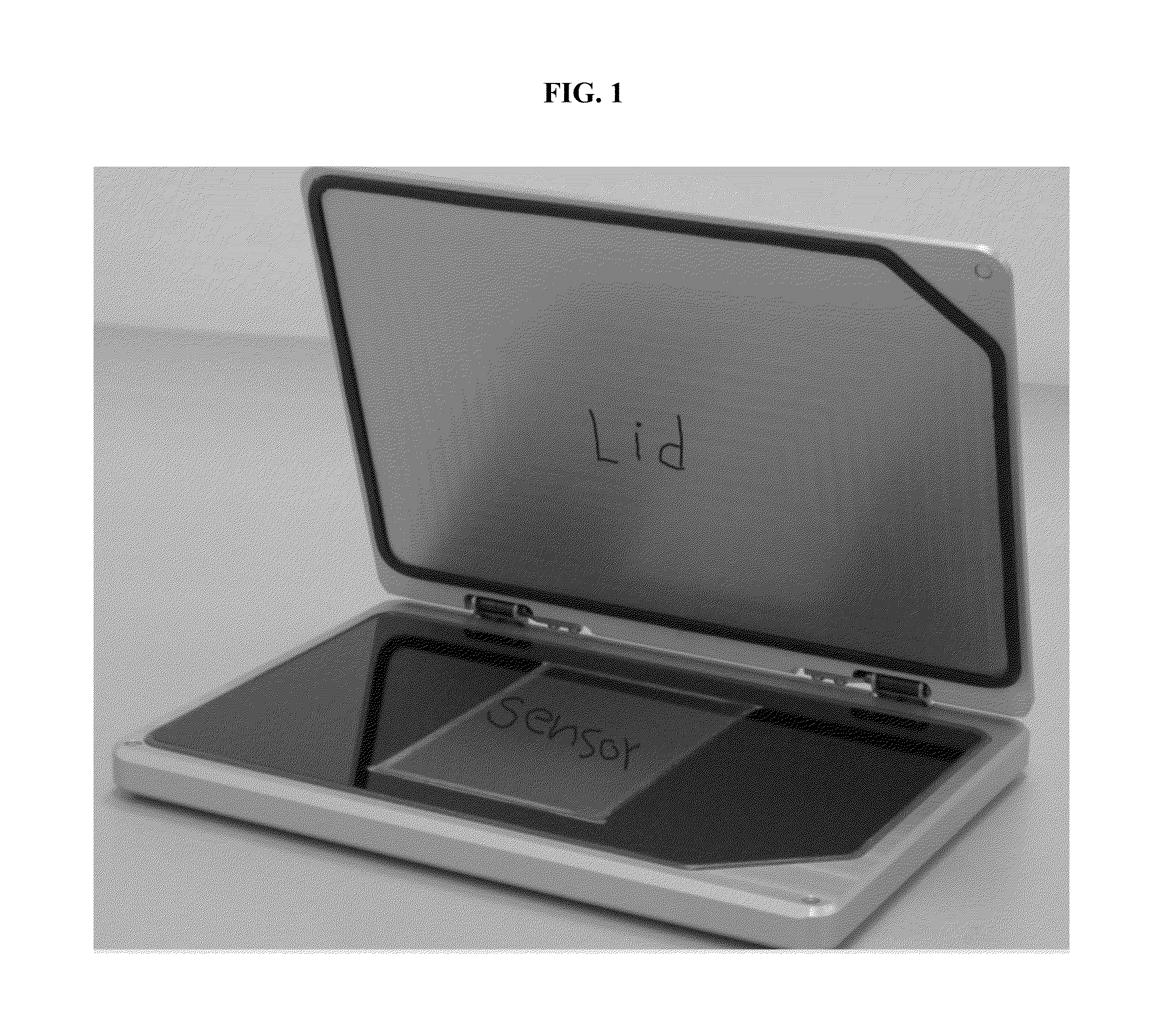
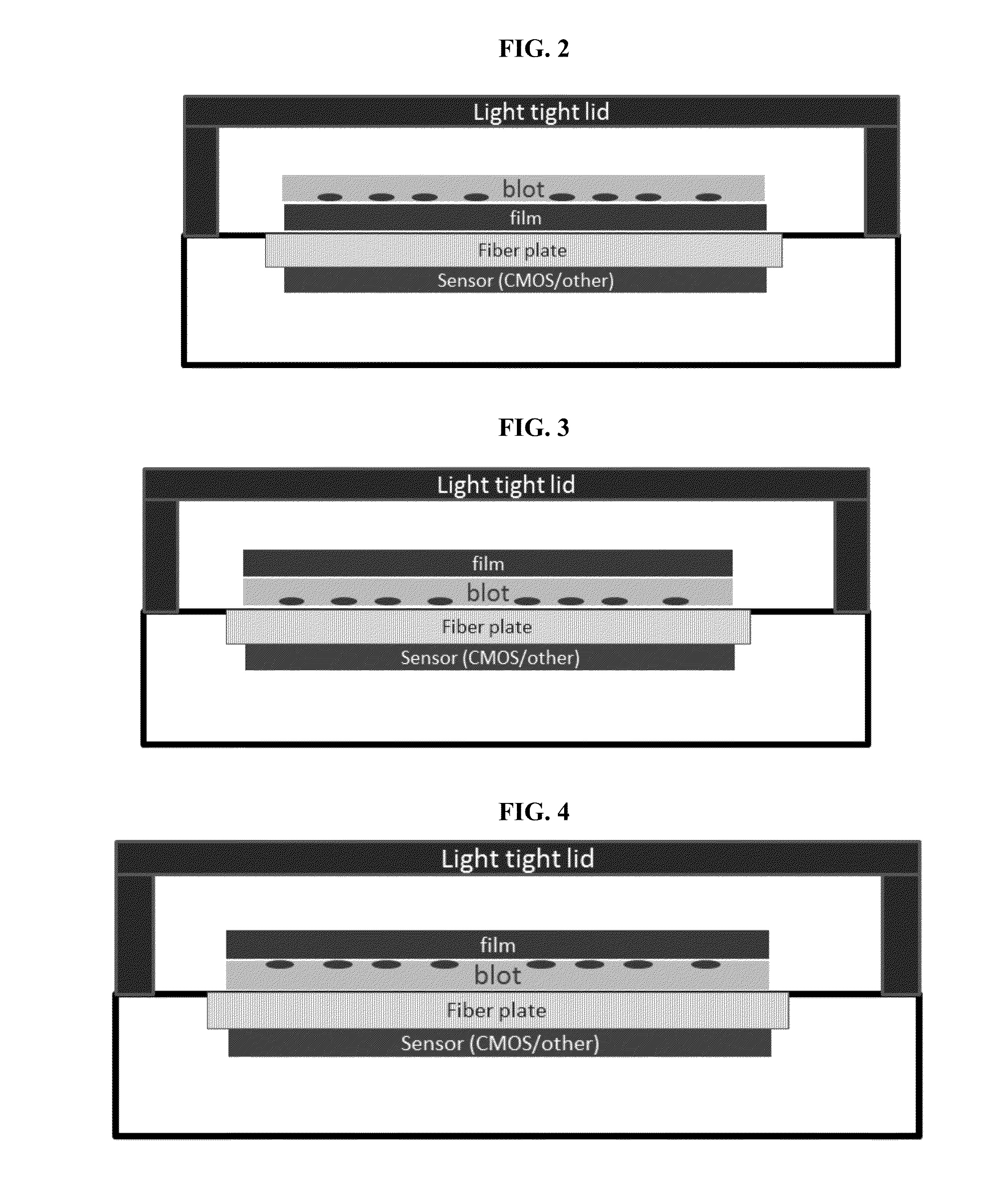
[0063]Examples of how the single-sensor device can be used are shown in FIGS. 2-4.

[0064]Both the film and the blot membrane are placed one on top the other inside the imaging cassette. The film can be placed below the blot (relative to the sensor) or above, as shown in FIGS. 2 and 3, respectively.

[0065]If the film is placed between the sensor and the blot (FIG. 2), light emitted from the bands on the blot has to pass through the film before it reaches the fiber face plate. While the light travels through the thickness of the film it can scatter slightly (depending on film thickness) leading to some degree of loss in image quality of the digital image (e.g., resolution), but obtaining maximum quality on the film image. This can be corrected with sharpening algorithms for the digital image.

[0066]If the blot is placed directly on the fiber plate with the sample side facing down (FIG. 3), the digital image would achieve maximal quality while...

example 2

Configurations for Use of Dual-Sensor Device

[0067]Examples of how the dual-sensor device can be used are shown in FIGS. 5-7.

[0068]FIG. 5 shows the blot sample side down on the fiber plate of the primary sensor and closed lid carrying the second sensor and fiber plate. Film can also be included with the dual-sensor device, as shown in FIGS. 6 and 7.

example 3

Effect of Sample Membrane Placement on Signal

[0069]A potential complication is interference of a membrane with signal, where the labeled analyte is on one side of the membrane and the sensor and / or film is on the other (non-analyte) side of the membrane. To determine if this would be an issue, we prepared a single membrane (8 cm×4 cm) and blotted with a dilution series, as shown in FIG. 8. The membrane was cut into identical halves, one placed in an imaging cassette with labeled analyte (sample) side up facing the film, the other placed in the imaging cassette with labeled analyte side down facing the fiber plate and sensor.

[0070]The membrane was developed using three different substrates: Westar® Supernova, Supersignal® West Femto, and Clarity™ substrates. The results are shown, respectively, in FIGS. 9-11.

[0071]The results show that the orientation of the membrane (sample-side up or down) has little effect on either digital or film images, especially at the higher concentrations.

[...


PUM


Abstract

Provided herein are imaging cassettes for detecting a luminescent and/or radioactive signals. Such cassettes are useful in common biological assays, e.g., immunoassays, nucleotide detection assays, and other affinity assays.

Description

CROSS-REFERENCE TO RELATED PATENT APPLICATIONS[0001]The present application claims benefit of priority to U.S. Provisional Patent Application No. 62 / 021,517, filed Jul. 7, 2014, which is incorporated by reference for all purposes.BACKGROUND OF THE INVENTION[0002]Traditionally, results from assays involving luminescent or radioactive labels would be obtained by exposing a blot, membrane, dried gel, etc. to X-ray film. After exposure, the film would be developed so the presence, absence, or intensity of signal from the assay could be determined. Film is convenient for recording results, provides crisp signal, and comparative results. Film results are not, however, quantitative. Moreover, a strong or weak signal can lead to overexposure or underexposure, respectively, so that the exposure must be repeated to obtain useful results. When the assay relies on a chemiluminescent signal that decays with time, it might not be possible to obtain results from a second or third exposure.[0003]Di...

Claims


Application Information

Patent Timeline
Patent Type & Authority Applications(United States)
IPC IPC(8): H04N5/225
CPCH04N5/2252G01N21/76G01N2201/0221G01N21/763H04N23/51
Inventor URI, YOCHANANRAN, BOAZBARAK, ITAYSWIHART, STEVENTHRUSH, EVAN
Owner BIO RAD LAB INC
Why Eureka
Try Eureka