Imaging unit

a technology of imaging unit and temperature rise, which is applied in the field of imaging units, can solve the problems of increasing failure risk of mounted components, increasing temperature rise associated with heat generated at components mounted inside stereo cameras, etc., and achieves the effect of suppressing temperature ris

Active Publication Date: 2016-01-07
RICOH KK
View PDF0 Cites 52 Cited by
  • Summary
  • Abstract
  • Description
  • Claims
  • Application Information

AI Technical Summary

Benefits of technology

[0010]According to the embodiment of the present application, an imaging unit, in which temperature rise can be suppressed, is provided.

Problems solved by technology

On the other hand, recently, upgrading and miniaturization of stereo cameras have been promoted, and a problem of a rise in temperature associated with heat generated at a component mounted inside a stereo camera has become evident.
When a temperature inside the stereo camera rises, a failure risk of the mounted component increases.

Method used


Image

  • Imaging unit
  • Imaging unit
  • Imaging unit

Examples


first embodiment

[0024]1>

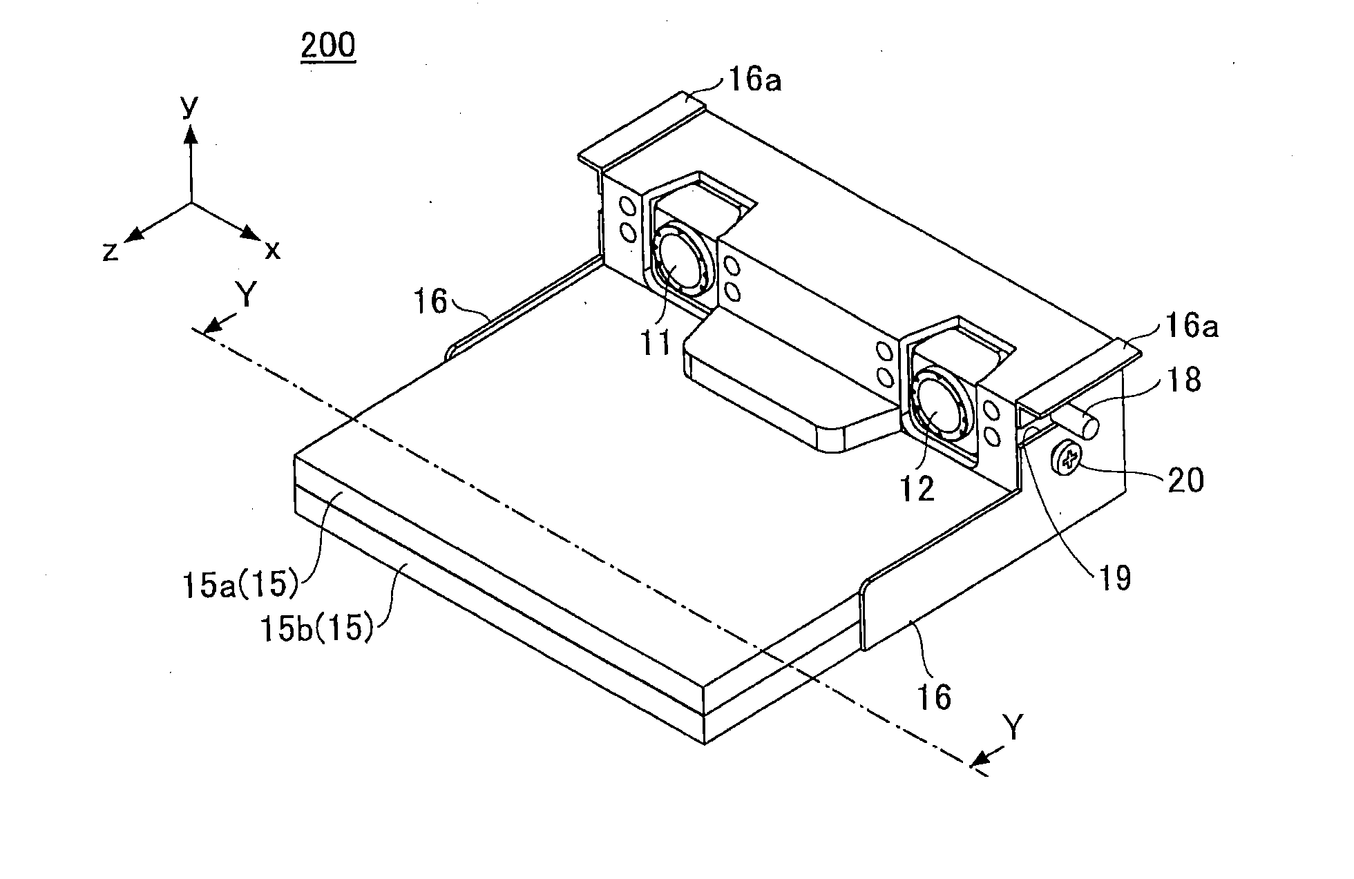
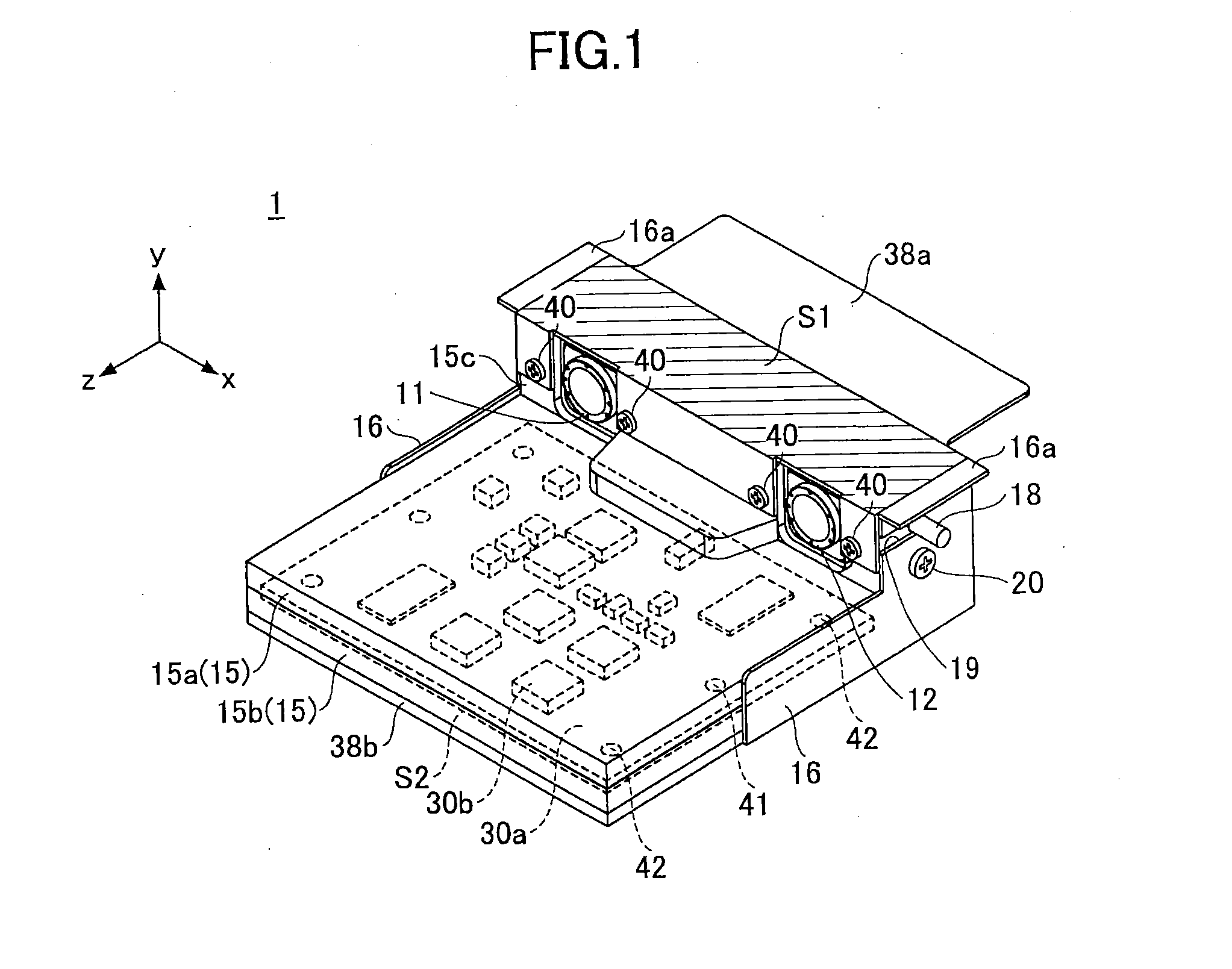
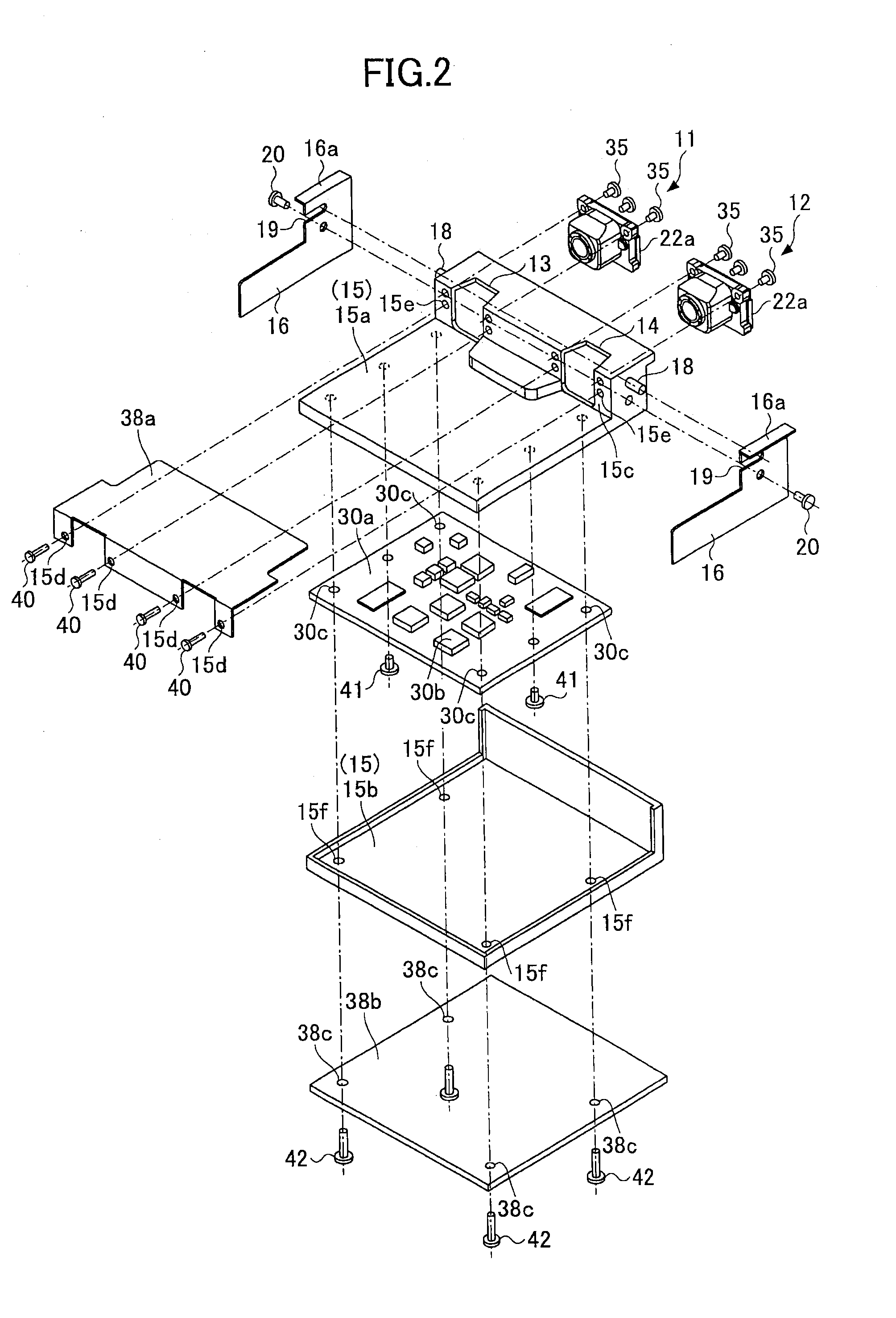
[0025]An overall configuration of an imaging unit 1 according to the present embodiment will be explained with reference to the drawings. FIG. 1 is a perspective diagram for explaining an example of the overall configuration of the imaging unit according to the first embodiment. Moreover, FIG. 2 is an exploded perspective diagram of the imaging unit shown in FIG. 1.

[0026]The imaging unit 1 includes, as shown in FIG. 1, plural (two in FIG. 1) monocular cameras (imaging devices) 11, 12; a chassis 15 for holding the monocular cameras 11, 12; and a circuit substrate. The imaging unit 1 further includes a heat transfer member provided in contact with the chassis 15 or the circuit substrate. The circuit substrate is housed inside the chassis 15.

[0027]The circuit substrate is configured by including respective imaging element substrates 22a of the monocular cameras 11, 12; and an image processing substrate 30a for processing images captured by the monocular cameras 11, 12. On each ...

second embodiment

[0077]In the first embodiment, the example in which the heat transfer members 38a, 38b are installed so as to contact the imaging element substrate 22a and the image processing substrate 30a via a separated member, such as the holder 31 or the chassis 15, is explained. However, the present invention is not limited to the above configuration. For example, the imaging element substrate 22a and the image processing substrate 30a may directly contact the heat transfer members 38a, 38b. FIGS. 6A and 6B are cross-sectional diagrams of the imaging unit according to a second embodiment. FIG. 6A illustrates an internal structure near the imaging element substrate. FIG. 6B illustrates an internal structure near the image processing substrate. Void arrows represent directions of heat transfers, respectively.

[0078]As shown in FIG. 6A, the heat transfer member 38a may be installed so as to directly contact the imaging element substrate 22a. For example, a position of the imaging element substrat...

third embodiment

[0080]In the first embodiment, the example in which the bracket 16 and the heat transfer members 38a, 38b are configured as separated members is explained. However, the present invention is not limited to the above configuration. For example, as shown in FIG. 7, it may be configured as a cover 150a, in which the heat transfer member 38b and the bracket are integrally formed by using the heat transfer member 38b as the bracket. In this case, the heat transfer member 38b can also be used as the heat transfer member 38a. An imaging unit 100 is installed by fixing the attachment portion 150b to the front windshield F by using an adhesive agent, a double-stick tape, a screw or the like. According to the above-described configuration, a number of components can be reduced, and thereby the imaging unit 100, which is low in cost and can prevent rise in temperature, is provided.

[0081]In this case, the heat of the imaging element 22b is transferred in the order of the imaging element substrat...


PUM


Abstract

An imaging unit includes a plurality of imaging devices configured to capture images of an object; a circuit substrate configured to generate image data based on the images captured by the imaging devices; a chassis that holds the imaging devices; and a heat transfer member including a contacting portion configured to contact an installed member in a case where the imaging unit is installed on the installed member. The heat transfer member contacts the chassis or the circuit substrate, and heat conductivity of the heat transfer member is greater than the heat conductivity of the chassis.

Description

BACKGROUND OF THE INVENTION[0001]1. Field of the Invention[0002]The disclosures herein generally relate to an imaging unit.[0003]2. Description of the Related Art[0004]Recently, image processing technologies have been remarkably improved. Moreover, since high-performance cameras became available at relatively low prices, applied technologies of cameras have been in practical use. For example, a stereo range finding technology, such as a stereo camera, in which plural cameras are mounted on a chassis and a distance to an imaged object is measured based on images captured by the respective cameras, has been known. Applications of the stereo range finding technology to various fields are examined.[0005]In the case of the stereo camera or the like, it is quite important to eliminate an influence of heat as much as possible so as to be accurate, irrespective of an installation environment. For example, Japanese Published Patent Application No. 2007-225543 discloses a configuration for re...

Claims


Application Information

Patent Timeline
Patent Type & Authority Applications(United States)
IPC IPC(8): H04N5/225H04N13/239G03B17/55
CPCH04N5/2253H04N13/0239G03B17/55H04N5/2257H04N5/2252G03B35/08H04N2213/001H04N13/239H04N23/52H04N23/51H04N23/54H04N23/50H04N23/57B60R2300/107B60R11/04H04N23/90
Inventor KIMURA, TOMONORIKAMBE, SHUYASUI, MAIKOTAKAMATSU, SHUJIADACHI, MASASHI
Owner RICOH KK
Why Eureka
Try Eureka