Anesthesia Compliant Volume System and Method

a volume system and anesthesia technology, applied in the field of anesthesia compliant volume system and method, can solve the problems of large range of liquid flow capability of valves, requiring vaporizers, and relatively high cost of valves, so as to increase the pressure of liquid and increase the effect of liquid pressur

Active Publication Date: 2016-01-14
GENERAL ELECTRIC CO
View PDF4 Cites 11 Cited by
  • Summary
  • Abstract
  • Description
  • Claims
  • Application Information

AI Technical Summary

Benefits of technology

[0004]An embodiment relates to a system for pressurizing and depressurizing liquid. The system includes a liquid reservoir, and a pump coupled to the liquid reservoir. The pump is configured to draw liquid from and return liquid to the liquid reservoir. A compliant volume coupled to the pump is configured to receive liquid from and return liquid to the pump. The compliant volume is composed of an elastic material to increase the pressure of the liquid as its volume is increased. The system includes a valve coupled to the compliant volume. The valve is configured to receive pressurized liquid from the compliant volume.
[0005]Another embodiment relates to a method for pressurizing liquid. The method includes drawing liquid by a pump from a liquid reservoir. The method also includes receiving liquid from a pump at a compliant volume coupled to the pump. Pressure of the liquid is increased based on the elastance of the compliant volume. The method includes receiving pressurized liquid from the compliant volume at a valve coupled to the compliant volume.

Problems solved by technology

One problem with some vaporizer systems is that a valve coupled to a vaporizer may be required to deliver varying flow rates of anesthetic liquid to the vaporizer.
In some cases, valves having a larger range of liquid flow capability may be relatively expensive when compared to valves having a smaller range of liquid flow.

Method used


Image

  • Anesthesia Compliant Volume System and Method
  • Anesthesia Compliant Volume System and Method
  • Anesthesia Compliant Volume System and Method

Examples


Embodiment Construction

[0012]In the following detailed description, reference is made to the accompanying drawings that form a part hereof, and in which is shown by way of illustration specific embodiments that may be practiced. These embodiments are described in sufficient detail to enable those skilled in the art to practice the embodiments, and it is to be understood that other embodiments may be utilized and that logical, mechanical, electrical and other changes may be made without departing from the scope of the embodiments. The following detailed description is, therefore, not to be taken as limiting the scope of the invention.

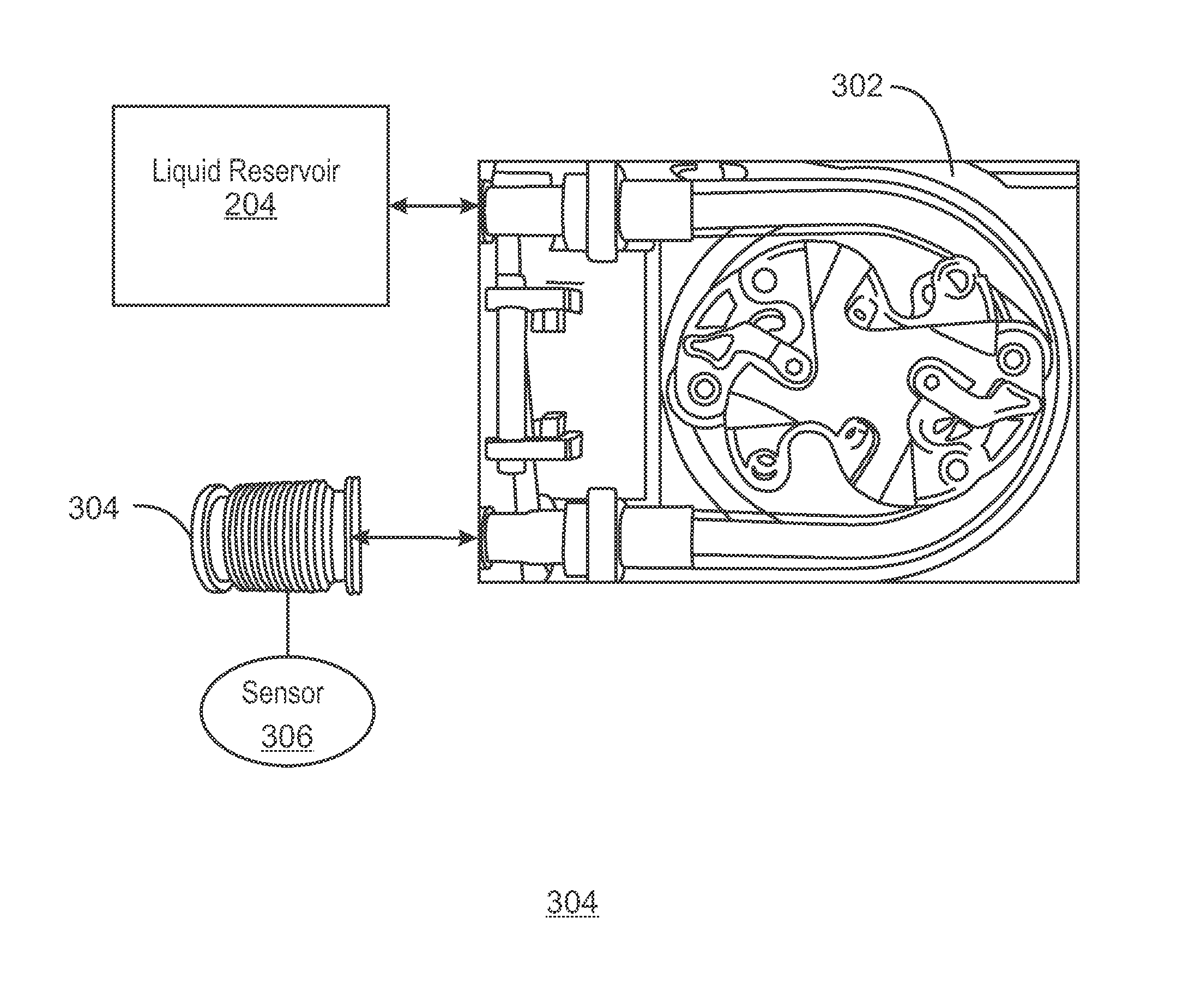
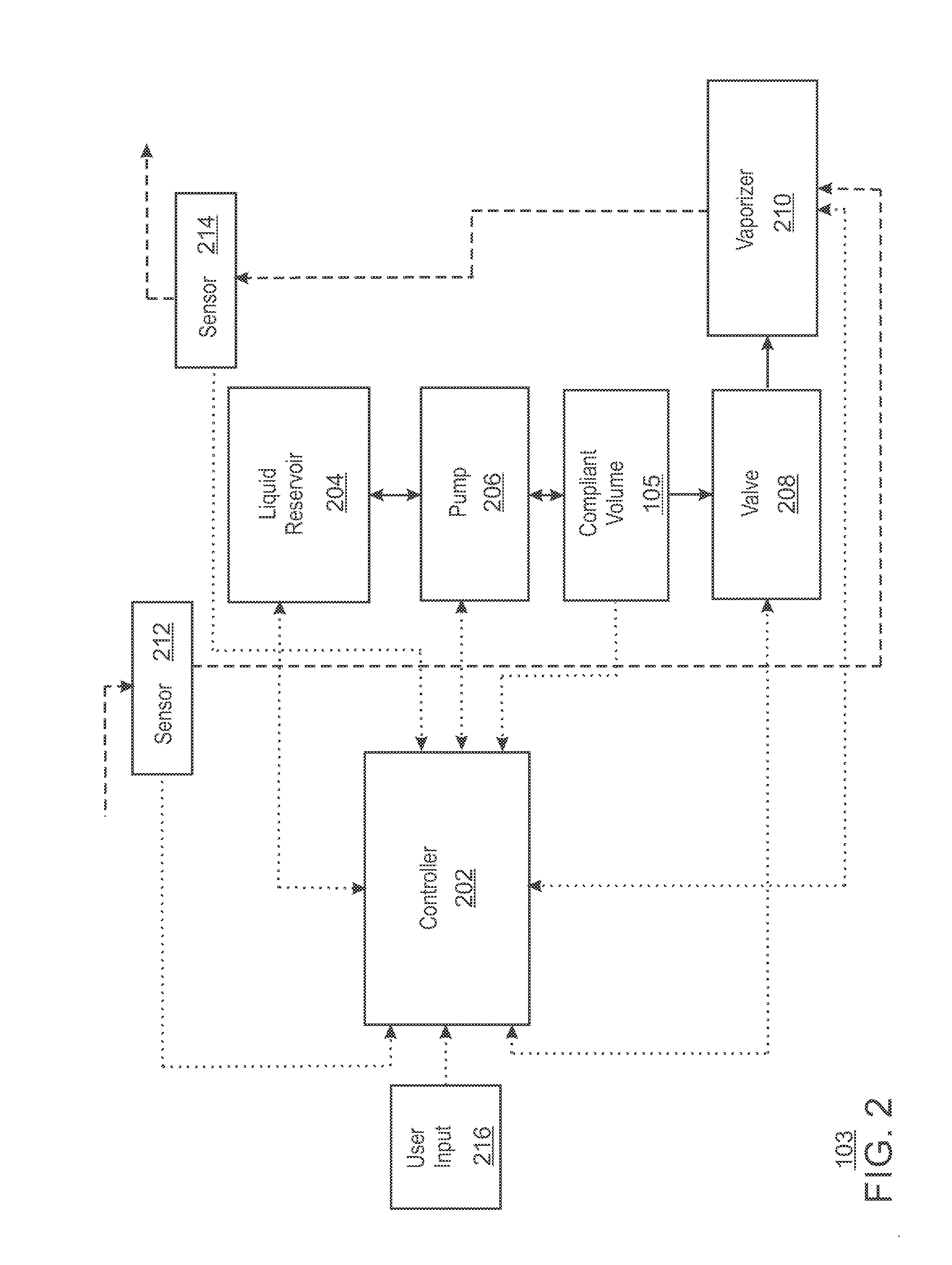
[0013]As discussed above, a valve coupled to a vaporizer may be required to deliver varying flow rates of anesthetic liquid to the vaporizer. In the embodiments discussed herein, a pump is coupled to a compliant volume. The compliant volume may be composed of a resilient and / or elastic material. As liquid is forced into the compliant volume, pressure of the liquid is increased...


PUM

PropertyMeasurementUnit
boiling pointaaaaaaaaaa
pressureaaaaaaaaaa
volumeaaaaaaaaaa

Abstract

A system for pressurizing liquid is described herein. The system may include a liquid reservoir and a pump coupled to the liquid reservoir, the pump to draw liquid from the liquid reservoir. A compliant volume coupled to the pump receives liquid from pump. The compliant volume is composed of an elastic material to increase pressure of the liquid. A valve coupled to the compliant volume receives pressurized liquid from the compliant volume.

Description

BACKGROUND[0001]Anesthesia may be administered to a patient in the form of a gas to produce an effect such as pain management, unconsciousness, preventing memory formation, and / or paralysis. A predetermined dosage of the administered anesthetic may be inhaled into the patient's lungs to produce one or more of these effects.[0002]Anesthesia systems may include an anesthesia machine coupled with a vaporizer system. Conventional vaporizer systems regulate anesthetic dosage in the gas phase. More precisely, some conventional vaporizer systems raise the temperature of the anesthetic to its vaporization point and thereafter regulate the concentration of delivered anesthetic gas such that the output concentration is maintained at a preselected target concentration.[0003]One problem with some vaporizer systems is that a valve coupled to a vaporizer may be required to deliver varying flow rates of anesthetic liquid to the vaporizer. In some cases, valves having a larger range of liquid flow ...

Claims


Application Information

Patent Timeline
Patent Type & Authority Applications(United States)
IPC IPC(8): A61M16/18A61M16/00A61M16/20B01F23/10
CPCA61M16/18A61M2205/3334A61M16/20A61M16/0075A61M11/045A61M16/127A61M16/203A61M16/0057A61M16/01A61M16/104A61M16/1075A61M2202/0283A61M2202/0208A61M2016/1035A61M2016/003A61M2205/505A61M2205/3673A61M2205/3653
Inventor BOTTOM, DOUGLAS, KIRK
Owner GENERAL ELECTRIC CO
Why Eureka
Try Eureka