Polishing device for optical elements and method thereof

a technology of optical elements and polishing discs, which is applied in the direction of optical surface grinding machines, manufacturing tools, prostheses, etc., can solve the problems of increasing processing costs, difficult to provide certain parameter processing, inaccurate control of contact pressure between polishing discs and workpieces, etc., to achieve the effect of reducing manufacturing costs and increasing processing accuracy and efficiency

Inactive Publication Date: 2016-01-14
ZHA JUN +5
View PDF20 Cites 12 Cited by
  • Summary
  • Abstract
  • Description
  • Claims
  • Application Information

AI Technical Summary

Benefits of technology

[0009]An object of the present invention is to provide a polishing device for optical elements and a method thereof, for increasing processing accuracy and efficiency, and lowering manufacturing costs.

Problems solved by technology

However, according to the device, control of a contact pressure between a polishing disc and a work piece is inaccurate with a large floating range.
Therefore, it is difficult to provide certain parameter processing.
Moreover, according to conventional polishing methods, work pieces with same curvature radius and same caliber require only one polishing disc base, but work pieces with different curvature radius or different calibers require different polishing disc bases, which increases a processing cost.
Therefore, how to accurately and efficiently process the aspheric optical elements has become an urgent problem to be solved.
However, processing costs thereof are unacceptable for the aspheric optical elements which are more and more widely applied.
Surface accuracy of optical elements processed by experienced works with high accuracy is also up to λ / 10, but efficiency is low and demands for aspheric optical elements are not satisfied.
However, because of a processing principle of copy processing, accuracy is largely limited by moulds, and materials to be processed are also limited.

Method used


Image

  • Polishing device for optical elements and method thereof
  • Polishing device for optical elements and method thereof
  • Polishing device for optical elements and method thereof

Examples


embodiment 1

Preferred Embodiment 1

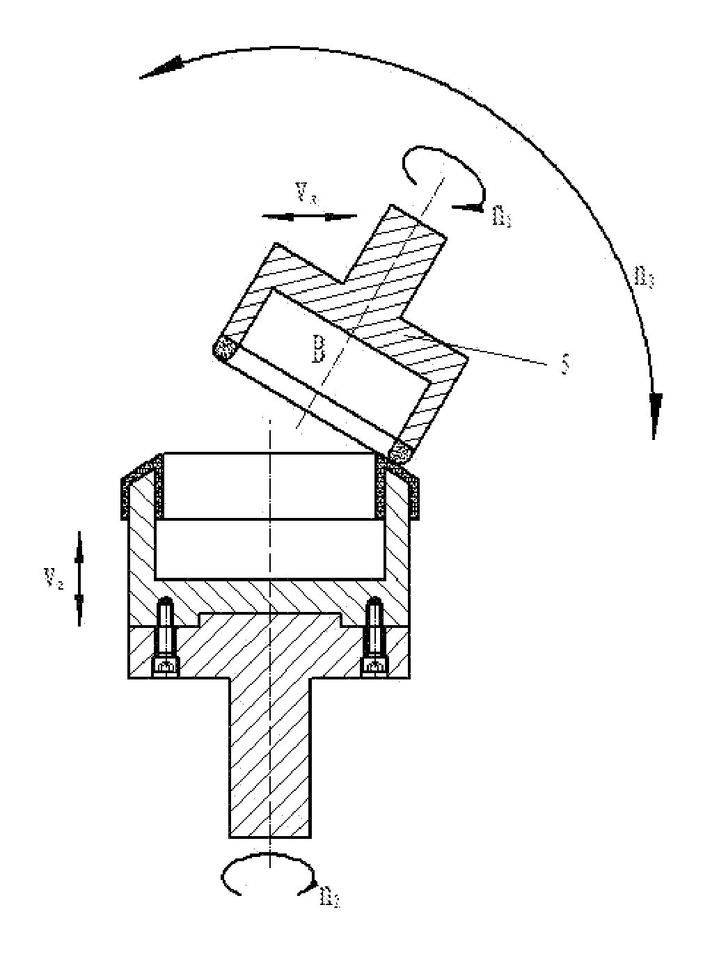
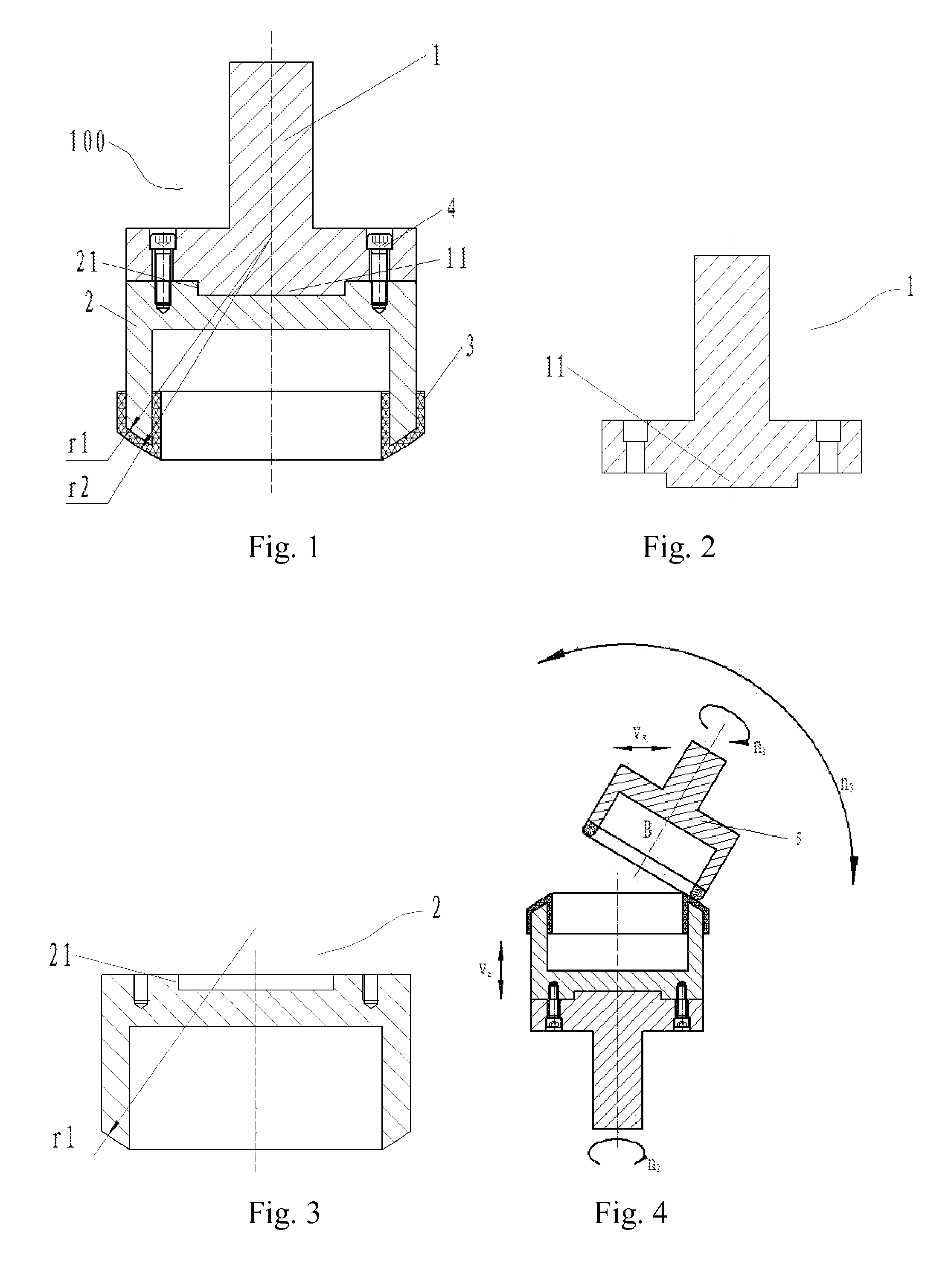
[0098]Referring to FIGS. 1-5, a polishing disc connecting rod 11 is at a bottom of a tool shank 1, which is able to be pressed into a polishing disc fixing port 21 at a top of a cylinder polishing disc base 2. During installing, the polishing disc connecting rod 11 is pressed into the polishing disc fixing port 21, and is fixed with the cylinder polishing disc base 2, in such a manner that there is no interval between the polishing disc connecting rod 11 and the polishing disc fixing port 21; wherein the tool shank 1 is fixed on the cylinder polishing disc base 2 by any spanner type, such as inner triangle, inner rectangle, inner hexagon, and double hole, which not only ensures connecting reliability therebetween, but also is convenient to install and maintain.

[0099]A polishing film 3 is stuck on an arc portion at a bottom of the cylinder polishing disc base 2. The polishing film 3 is selected according to a material of the unprocessed work piece 6. There is no...

embodiment 2

Preferred Embodiment 2

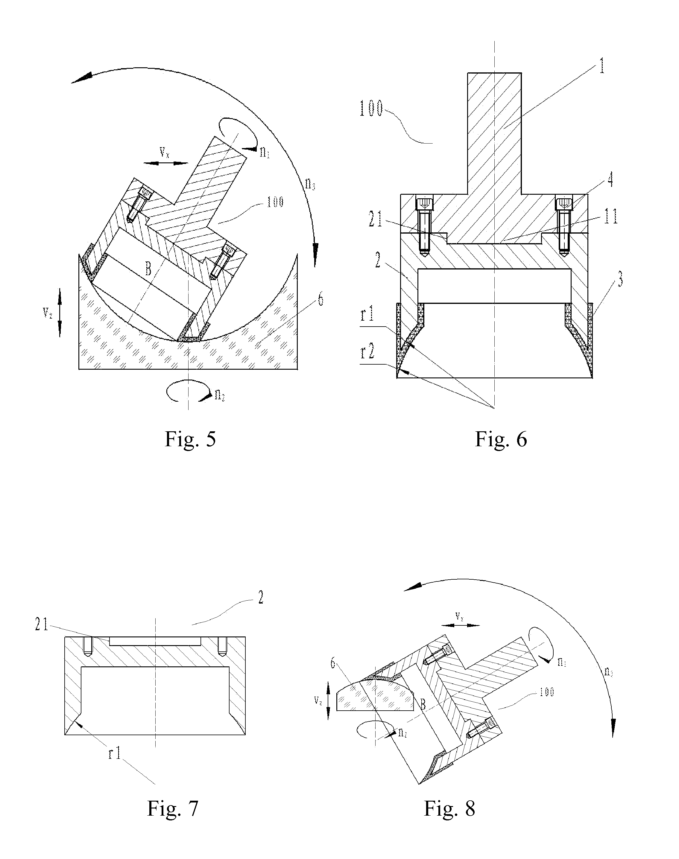
[0103]FIG. 6 is a sketch view of a polishing device 100 according to the preferred embodiment 2, wherein a tool shank 1 and a cylinder polishing disc base 2 are respectively illustrated in FIGS. 2 and 7. Accordingly, the polishing device 100 comprises: a tool shank 1 for installing a cylinder polishing disc; a cylinder polishing disc base 2 for sticking a polishing film 3; and the polishing film 3 for contacting with an unprocessed work piece 6 (not shown) for polishing. The preferred embodiment 2 is suitable for polishing convex elements, and installation and trimming of the polishing film 3 are the same with the preferred embodiment 1 and will not be described again.

[0104]FIG. 8 illustrates polishing the convex element according to the preferred embodiment 2, and a utilization method thereof is the same as the one of the preferred embodiment 1 and will not be described again.

embodiment 3

Preferred Embodiment 3

[0105]FIG. 9 is a sketch view of a polishing device 100 according to the preferred embodiment 3, wherein a tool shank 1 and a cylinder polishing disc base 2 are respectively illustrated in FIGS. 2 and 10. Accordingly, the polishing device 100 comprises: a tool shank 1 for installing a cylinder polishing disc; a cylinder polishing disc base 2 for sticking a polishing film 3; and the polishing film 3 for contacting with an unprocessed work piece 6 (not shown) for polishing. The preferred embodiment 2 is suitable for polishing planar elements, and installation and trimming of the polishing film 3 are the same with the preferred embodiment 1 and will not be described again. The preferred embodiment 3 is a specific type of the preferred embodiment 1 and 2, which is a special case when curvature radius of the arc portion of the polishing disc base in the preferred embodiment 1 or 2 tends to be infinity.

[0106]FIG. 11 illustrates polishing the convex element according ...


PUM


Abstract

A polishing device for optical elements includes: a tool shank (1), and a polishing disc base; wherein the tool shank (1) is connected to the polishing disc base and is mounted on a tool shaft of a numerical-controlled processing device; wherein a polishing film (3) is stuck on the polishing disc base; the polishing disc base is a profiling polishing disc base (7), a cylinder polishing disc base (2), a profiling polishing disc base (12) or a spherical polishing disc base (8); wherein the tool shank (1) is independent and universal, thereby reducing the processing cost of the polishing device. A polishing method for optical elements is based on the shapes mentioned above of the polishing disc base.

Description

CROSS REFERENCE OF RELATED APPLICATION[0001]This is a U.S. National Stage under 35 U.S.C 371 of the International Application PCT / CN2014 / 076076, filed Apr. 24, 2014, which claims priority under 35 U.S.C. 119(a-d) to CN 201320123777.8, filed Mar. 19, 2013; CN 201320124181.X, filed Mar. 19, 2013; and CN 201320123105.7, filed Mar. 19, 2013.BACKGROUND OF THE PRESENT INVENTION[0002]1. Field of Invention[0003]The present invention relates to optical element processing, and more particularly to a polishing device for optical elements and a method thereof.[0004]2. Description of Related Arts[0005]Conventional polishing techniques for spherical and planar optical elements are mainly high-speed polishing based on a quasi sphere center method. Devices thereof are cheap and operations are simple. However, according to the device, control of a contact pressure between a polishing disc and a work piece is inaccurate with a large floating range. Therefore, it is difficult to provide certain parame...

Claims


Application Information

Patent Timeline
Patent Type & Authority Applications(United States)
IPC IPC(8): B24B9/14
CPCB24B9/14B24B13/0018B24B13/012B24B13/02B24B9/146B24B9/148B24B13/0006B24B13/0012B24B13/005B24B13/026B24B13/06
Inventor CHEN, YAOLONGZHANG, CHUANCHEN, XIAOYANZHA, JUN
Owner ZHA JUN
Why Eureka
Try Eureka