Method for automatically triggering a self-positioning process

a self-localization and process technology, applied in the direction of distance measurement, programme control, instruments, etc., can solve the problems of delayed execution of tasks and long time-consuming self-localization process carried out according to such a method

Active Publication Date: 2016-01-14
ROBART
View PDF6 Cites 39 Cited by
  • Summary
  • Abstract
  • Description
  • Claims
  • Application Information

AI Technical Summary

Problems solved by technology

However, a self-localization process which is carried out according to such a method may last for a very long time, depending on the size and number of available maps.
During this time, the robot is partially shut down for its actual task, for example approaching a destination, as a result of which the execution of tasks is delayed.

Method used


Image

  • Method for automatically triggering a self-positioning process
  • Method for automatically triggering a self-positioning process
  • Method for automatically triggering a self-positioning process

Examples


Embodiment Construction

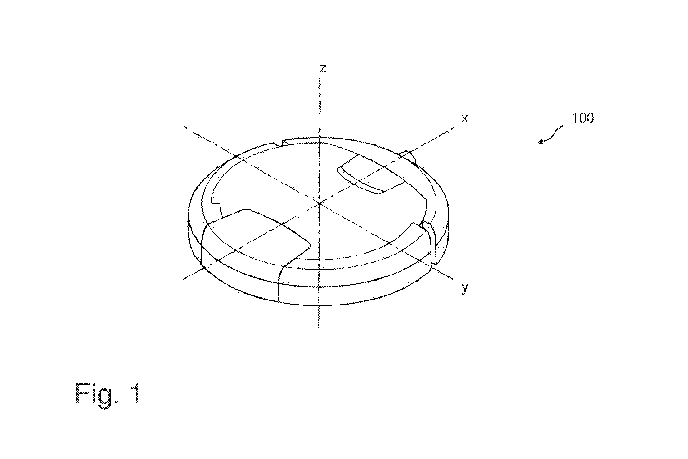
[0018]FIG. 1 shows, by way of example, a schematic isometric illustration of a self-propelled robot 100 for autonomously cleaning floor areas. FIG. 1 also shows a Cartesian coordinate system with the origin in the center of the robot 100. Such devices are often—but not necessarily—in the form of a disk. The vertical axis z passes through the center of the disk. The longitudinal axis is denoted with x and the transverse axis is denoted with y.

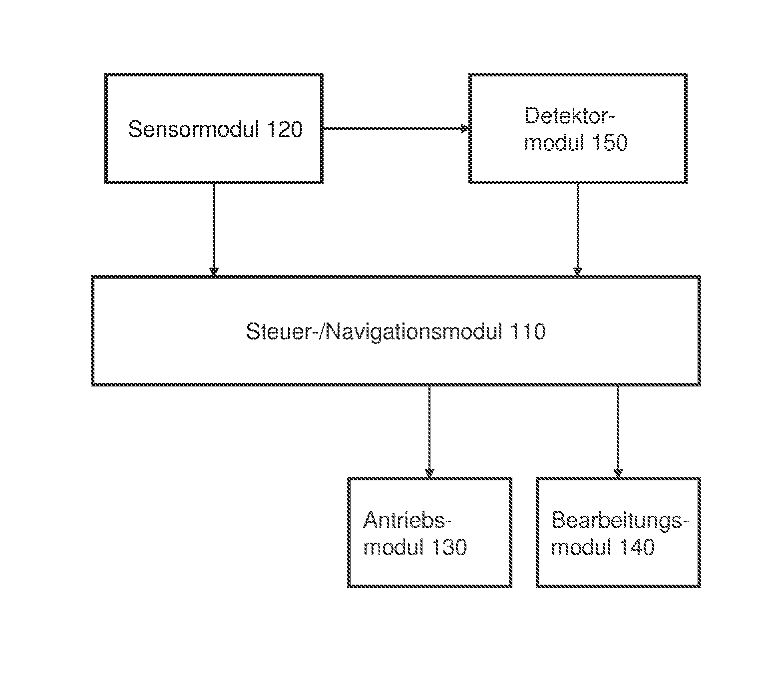
[0019]The robot 100 comprises a drive module (not illustrated) which may have electric motors, gears and wheels, for example. The drive module may be designed, for example, to move the robot in the forward and reverse directions (this would be along the x axis in the illustration from FIG. 1) and to rotate the robot about the vertical axis (this would be the z axis in the illustration from FIG. 1). Therefore, the robot can—theoretically—approach any point of a floor area (which is parallel to the plane defined by the x axis and y axis). The robo...


PUM


Abstract

A mobile self-propelled robot for autonomously carrying out actions. The robot includes a drive module for moving the robot over a floor area; a processing module for carrying out the activities during a processing stage; at least one sensor module for detecting information relating to the structure of the surroundings; a detector module configured to detect a displacement of the robot prior to or during the processing stage. Further, the robot includes a navigation module configured to navigate the robot over the floor area during the processing stage using a map of the surroundings, to store and manage one or more maps of the surroundings, and to carry out a self-positioning process if the detector module has detected a displacement of the robot. During the self-positioning process, the presence and the location of the robot within the stored maps are detected.

Description

TECHNICAL FIELD[0001]The present description relates to a method for automatically triggering a self-localization process, in particular an automatic global self-localization process of a self-propelled autonomous robot (for example robotic vacuum cleaners).BACKGROUND[0002]Numerous self-propelled robots for cleaning or treating floor areas are known and are commercially available. In principle, the intention is to treat the floor area as completely as possible in the shortest possible time. Random navigation methods are used in simple systems (for example EP 2287697 A2 by iRobot Corp.), which methods manage without creating or using a map of the environment in which the floor area to be treated is situated. That is to say, no local information relating to obstacles, floor area boundaries, cleaned / uncleaned areas, etc. is used. In combination with local movement strategies, only the direction of travel is (randomly) changed in the event of a collision with an obstacle. As a result, r...

Claims


Application Information

Patent Timeline
Patent Type & Authority Applications(United States)
IPC IPC(8): B25J9/16B25J5/00B25J11/00G05D1/02
CPCB25J9/1692B25J5/00Y10S901/01B25J11/0085G05D1/0274B25J9/1664G05D2201/0203
Inventor ARTES, HAROLDSEETHALER, DOMINIKSCHAHPAR, MICHAEL
Owner ROBART
Why Eureka
Try Eureka