
Eureka
For R&D, Eureka makes reading and utilizing patents & technical documents easy.
Eureka AIR
Designed for self-driven R&D workflows. Generate viable solutions, solve complex R&D challenges, empower your innovation with AI.

Eureka Materials
Designed for material experts only. Revolutionize your material R&D, from search, analyze, to developing new materials.

TechResearch
Generate reliable direction feasibility study reports for your R&D in just a few steps.

TechSeek
Discover and master advanced knowledge NOW. Basics, ideas, possibilities, all at once.

TechMind
As an expert in R&D Theories, TechMind can generates customized viable solutions instantly.

TechRisk
Analyze your overall solution with one click, know your potential R&D risks in advance.

TechMonitor
Get weekly tech updates, stay abreast of the latest tech innovations and key insights.
Sterilization device for container
- Summary
- Abstract
- Description
- Claims
- Application Information
AI Technical Summary
Benefits of technology
Problems solved by technology
Method used
Image

Examples
first embodiment
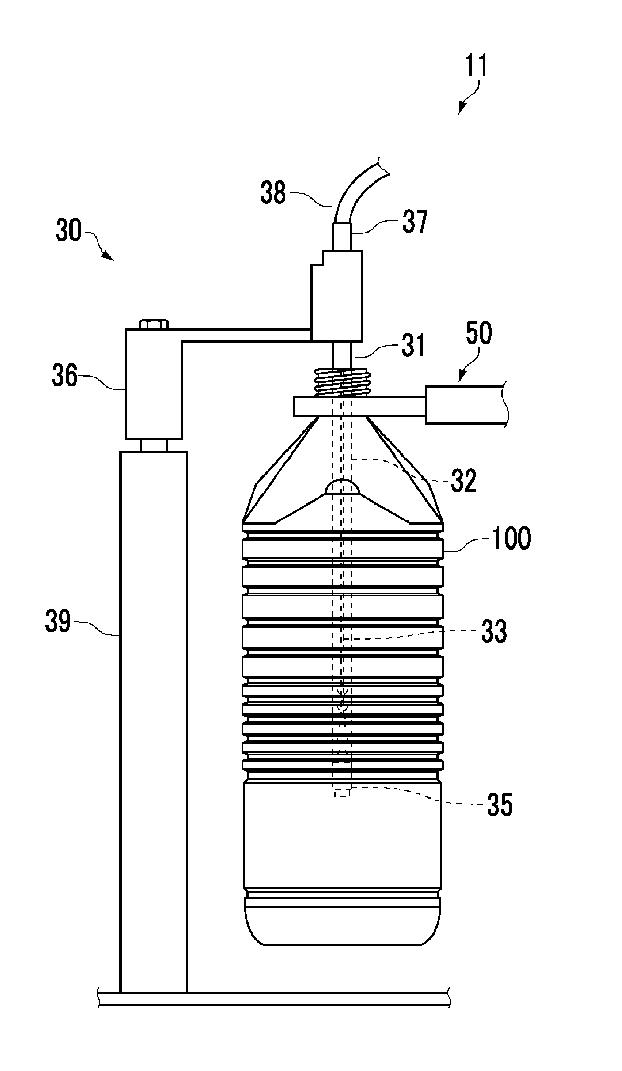
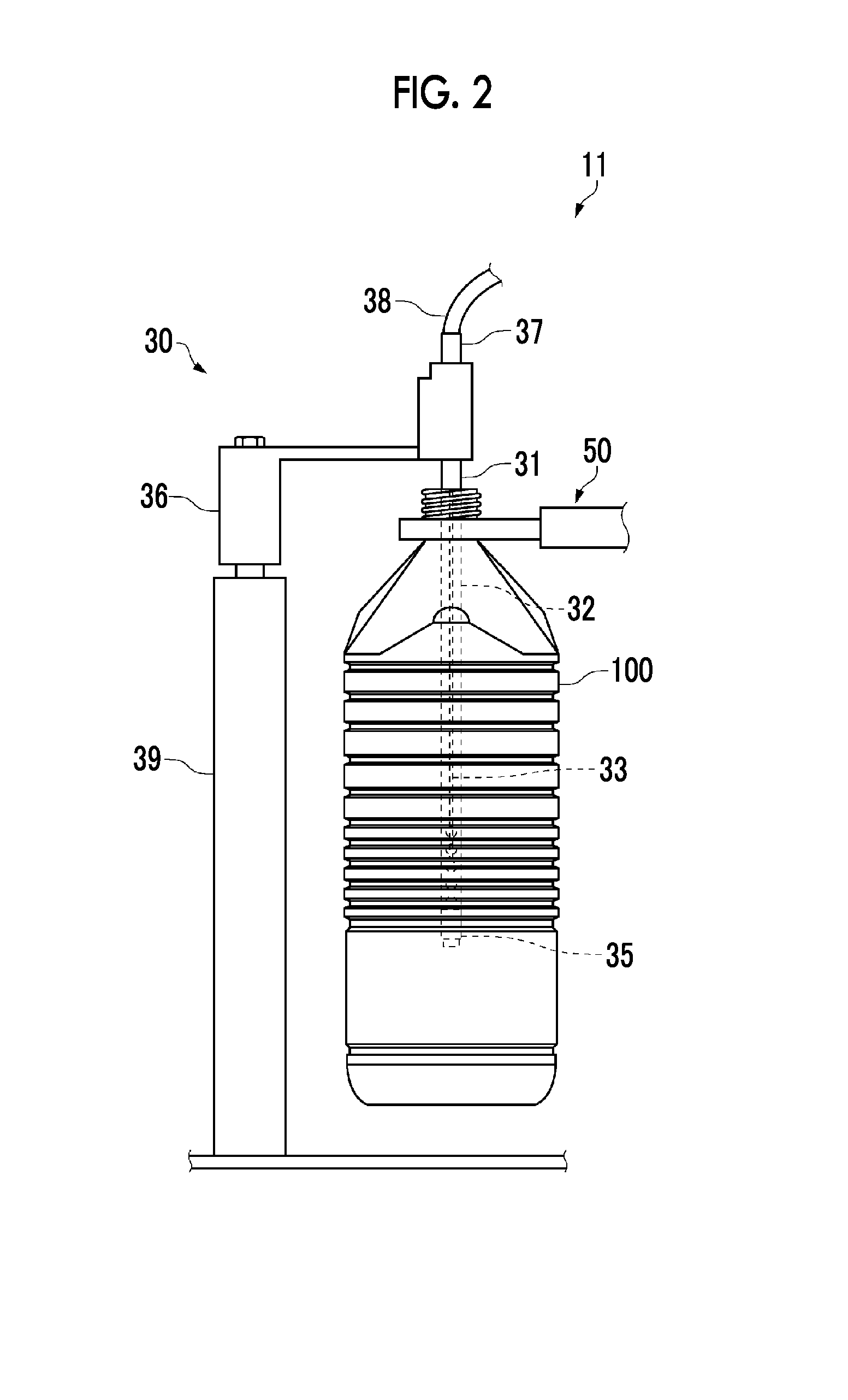
[0025]Hereinafter, a sterilization device for a container of the invention will be described on the basis of an embodiment applied to an aseptic beverage filling machine.
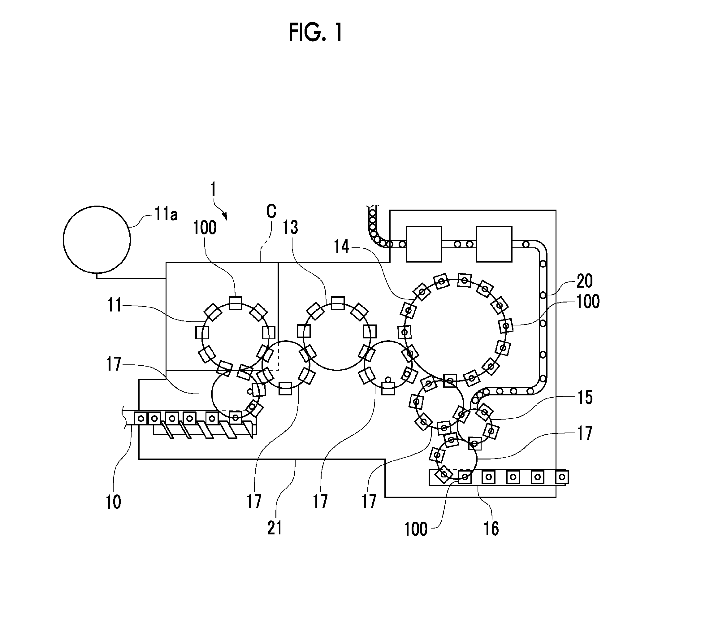
[0026]As illustrated in FIG. 1, an aseptic beverage filling machine 1 includes, as constituent elements, an importing conveyor 10 which imports a container 100 to the aseptic beverage filling machine 1, a sterilization device 11 which sterilizes the container 100, a rinsing device 13 which rinses the container 100, a filling device 14 which fills the container 100, which is subjected to sterilization and rinsing, with a liquid (beverage), a capper 15 which attaches a cap 20 to the container 100 filled with the beverage, and an exporting conveyor 16 which exports the container 100 to the outside of the aseptic beverage filling machine 1. Transporting star wheels 17 are provided between the constituent elements so that the container 100 can be transported between the constituent elements.
[0027]The transport path of th...
second embodiment
[0070]Next, a second embodiment of the invention will be described with reference to FIGS. 7 to 8(c). The second embodiment is similar to the first embodiment in that the sterilant is vaporized in the container 100 and is different therefrom in means for vaporizing the sterilant. Hereinafter, the second embodiment will be described focusing on the differences therebetween.
[0071]In the second embodiment, when sterilization is performed, a sterilant supply tube 41 of a sterilant supply unit 40 is inserted into the inverted container 100 from below. When sterilization is ended, the sterilant supply tube 41 is lowered and removed from the container 100.
[0072]As illustrated in FIGS. 7 to 8(c), the sterilant supply tube 41 includes a hollow cylindrical tube body 42, a needle 43 which is disposed inside the tube body 42 to discharge the sterilant toward a heating medium 44, and a nozzle 37 which supplies the sterilant to the needle 43. In addition, even in the second embodiment, a side on ...
PUM
 Abstract
Description
Claims
Application Information
 - R&D Engineer
- R&D Manager
- IP Professional
- Industry Leading Data Capabilities
- Powerful AI technology
- Patent DNA Extraction
Browse by: Latest US Patents, China's latest patents, Technical Efficacy Thesaurus, Application Domain, Technology Topic, Popular Technical Reports.
© 2024 PatSnap. All rights reserved.Legal|Privacy policy|Modern Slavery Act Transparency Statement|Sitemap|About US| Contact US: help@patsnap.com