
Applicator

Inactive Publication Date: 2016-01-14
MITSUBISHI PENCIL CO LTD
View PDF7 Cites 3 Cited by
  • Summary
  • Abstract
  • Description
  • Claims
  • Application Information

AI Technical Summary

Benefits of technology

The present invention provides an applicator with a simple structure that improves fitting force to prevent the sealing element from coming off. The applicator includes an inner cap with a hinged cap that can be opened and closed and an engagement structure to securely hold the inner cap in place. The opening of the applying part is 0.2 mm2 or greater and the application liquid contains solids content of 5% by weight or greater as a coating component. The patent aims to provide a practical and efficient solution for applying various liquids to surfaces.

Problems solved by technology

When used with a high viscosity or adhesive content liquid, these applicators entail risk that the writing tip and the sealing element stick to each other, causing the sealing element to come off or be dislodged.
In this case, if the tip of the applying part comes into liquid contact with the sealing rubber and becomes stuck, the sticking may produce a greater bonding force than the fixing force, causing the sealing rubber to come off from the cap.
When undercuts and face-cutting are used to improve the fitting strength, provision of fitting margins exceeding a predetermined amount is considered to be impossible because assembly of the sealing rubber into the inner cap becomes infeasible.
However, the method disclosed in Patent Document 1 uses a sealing element of a complicated configuration so that use of thermoplastic elastomer is required, hence needing extra steps and effort such as application of heat and the like.

Method used


Image

  • Applicator
  • Applicator
  • Applicator

Examples


first embodiment

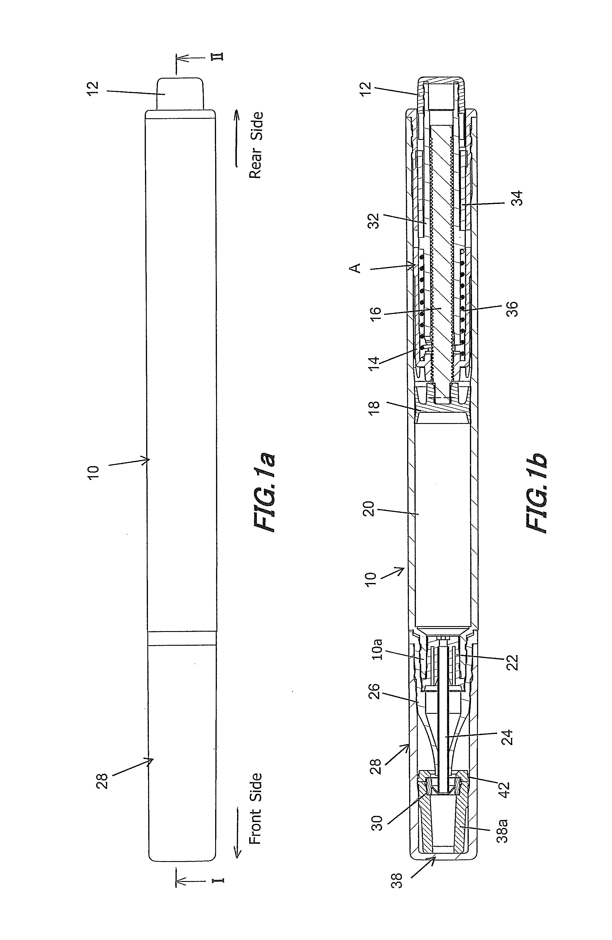
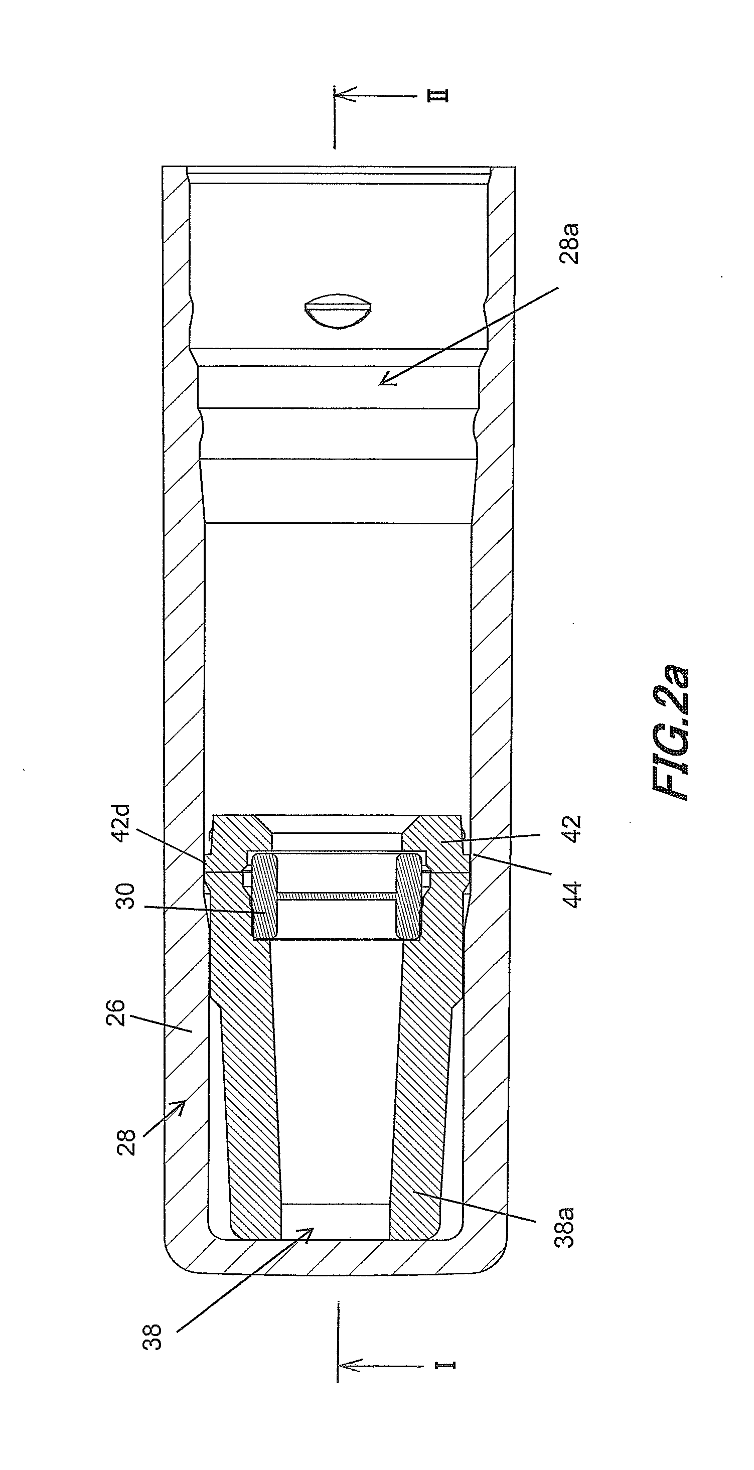
[0097]FIGS. 1a to 5b are illustrative diagrams of an applicator provided with the cap according to the present invention.

[0098]Here, in the following description, FIGS. 1a and 1b may also be collectively referred to as FIG. 1. FIGS. 2a and 2b may also be collectively referred to as FIG. 2. FIGS. 3a to 3h may also be collectively referred to as FIG. 3. FIGS. 4a to 4f may also be collectively referred to as FIG. 4. FIGS. 5a and 5b may also be collectively referred to as FIG. 5.

[0099]The applicator according to the first embodiment is a click-feed container that can feed contents by pushing a click cover 12 arranged at rear end of a barrel body (barrel cylinder) 10 forward in the axial direction, as shown in FIG. 1.

[0100]In the following description of the applicator of FIG. 1, the cap 28 side will be referred to as the front side with respect to the extended direction (axial direction) of the axis of the applicator, whereas the click cover 12 side will be called the rear side with res...

second embodiment

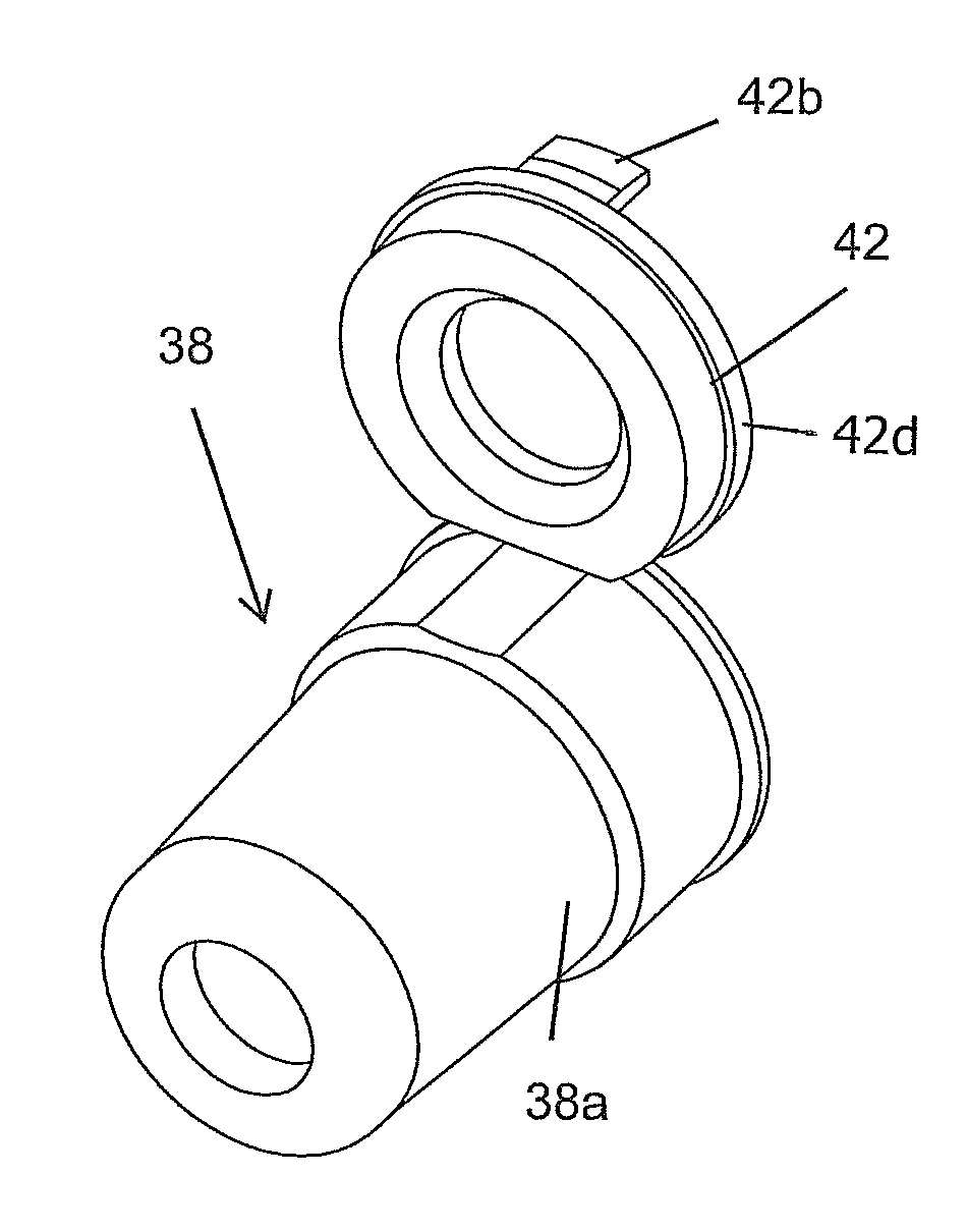
[0150]As shown in FIGS. 6 to 8, in the applicator an engagement structure 46 (FIGS. 7f and 7g) is provided between the hinged cap 42 and the inner cap body 38a. With the sealing element 30 held therebetween, hinged cap 42 is folded at the hinge structure 40 so that the hinged cap 42 and the inner cap body 38a can be engaged with each other by the engagement structure 46.

[0151]Specifically, the engagement structure 46 is comprised of projections 46a on the hinged cap 42 side and ribs 46b on the inner cap body 38a side.

[0152]As to the projections 46a on the hinged cap 42 side, the hooking part 42b of the hinged cap 42 has a rounded semicylindrical projection 46a projected in the width direction on both sides with respect to the width direction, as enlarged shown in FIGS. 7g and 8g (FIGS. 8d to 8g).

[0153]As to the ribs 46b on the inner cap body 38a side, with the inner cap body 38a closed by the hinged cap 42, ribs 46b that extend in the circumferential direction opposing projections ...


PUM


Abstract

An applicator includes: an applying part on a front portion thereof; a removable cap that totally covers the applying part; a sealing element that seals up a front end portion of the applying part when the cap is fitted; and an inner cap provided inside the cap. The inner cap includes an inner cap body and a hinged cap that is joined to the inner cap body and can abut the inner cap body. The hinged cap has a hollow mounting portion. An engaging portion for fixing the hinged cap is formed inside the cap. When the inner cap having the sealing element held between the inner cap body and the mounting portion is fitted into the interior of the cap, the hinged cap is engaged by the engaging portion inside the cap.

Description

[0001]This Nonprovisional application claims priority under 35 U.S.C. §119 (a) on Patent Application No. 2014-144236 filed in Japan on 14 Jul. 2014, the entire contents of which are hereby incorporated by reference.BACKGROUND OF THE INVENTION[0002](1) Field of the Invention[0003]The present invention relates to a feed type applicator with an applying part covered by a cap.[0004](2) Description of the Prior Art[0005]Conventionally, there have been applicators that have a writing tip sealed up by a sealing element arranged on a cap when the cap is fitted, as disclosed in Patent Documents 1 to 5.[0006]When used with a high viscosity or adhesive content liquid, these applicators entail risk that the writing tip and the sealing element stick to each other, causing the sealing element to come off or be dislodged.[0007]In order to solve this problem, it is necessary to take measures to prevent the sealing element from coming off by improving the strength of engagement between the sealing e...

Claims


Application Information

Patent Timeline
IPC IPC(8): B65D43/16B65D43/02B65D43/22B65D51/18
CPCB65D43/02B65D43/16B65D43/22B65D51/18B65D2251/009B65D2251/0028B65D2251/0059B65D2251/0084B65D2251/0015B43K23/08B43K29/02B43K29/05
Inventor MIYAMOTO, KOHEIUEHARA, JUNYA
Owner MITSUBISHI PENCIL CO LTD
Features
  • Generate Ideas
  • Intellectual Property
  • Life Sciences
  • Materials
  • Tech Scout
  • Unparalleled Data Quality
  • Higher Quality Content
  • 60% Fewer Hallucinations
Learn More