System and method for controlling exhaust emissions and specific fuel consumption of an engine

a technology of specific fuel consumption and exhaust emissions, which is applied in the direction of electrical control, process and machine control, instruments, etc., can solve the problems of reducing the fuel consumption of diesel engines in mountainous regions, affecting the performance of diesel engines, and affecting the efficiency of diesel engines, so as to achieve specific fuel consumption of engines

Active Publication Date: 2016-01-14
GE GLOBAL SOURCING LLC
View PDF11 Cites 22 Cited by
  • Summary
  • Abstract
  • Description
  • Claims
  • Application Information

AI Technical Summary

Benefits of technology

The technical effect of this patent is to provide better control over how an engine produces exhaust gases and uses fuel.

Problems solved by technology

This patent relates to a problem faced by compression-ignition engines, especially those operated in extreme environments such as mountaintops. These conditions can negatively influence engine performance, efficiency, exhaust polluants, and other factors that determine how well the engine operates. There is a technical need for better ways to manage these engines to limit harmful emissions while still maintaining optimal performance under challenging circumstances.

Method used


Image

  • System and method for controlling exhaust emissions and specific fuel consumption of an engine
  • System and method for controlling exhaust emissions and specific fuel consumption of an engine
  • System and method for controlling exhaust emissions and specific fuel consumption of an engine

Examples


Embodiment Construction

[0016]The term “Tier 4” or “Tier 4 standards” means the Tier 4 Line Haul Locomotive Emissions Standards as promulgated by the United States Environmental Protection Agency (EPA). The Tier 4 standards are codified at 40 CFR Part 1033, while the de facto standards and Tables are found specifically at 40 CFR 1033.101. Tier 4 standards can also be found at http: / / www.ecfr.gov / cgi-bin / text-idx?SID=c96b8ff349cc19252400485a86e87e99&mc=true&node=se40.33.1033—1101&rgn=div8. The Tier 4 standards are incorporated herein by reference in their entirety.

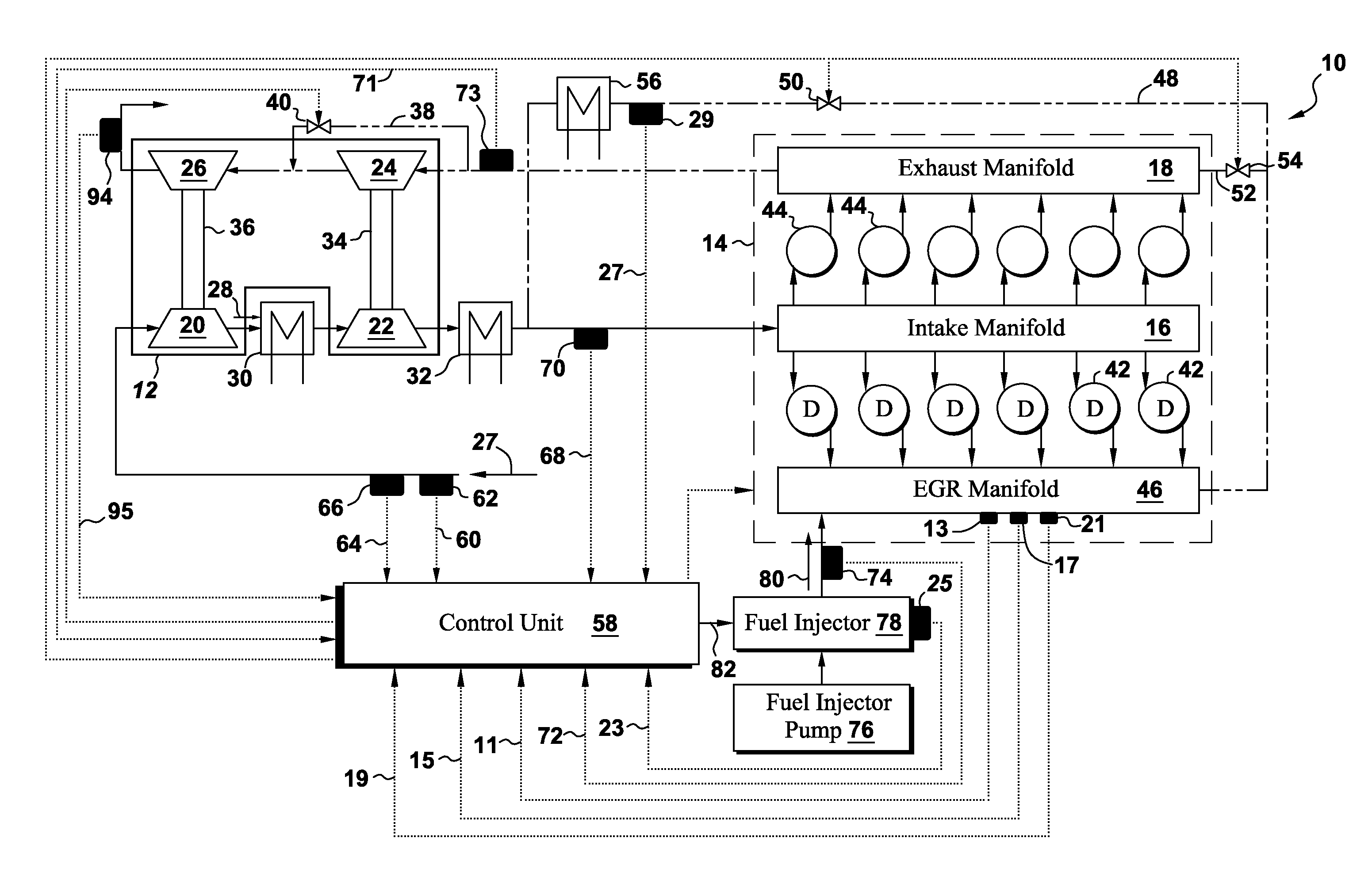
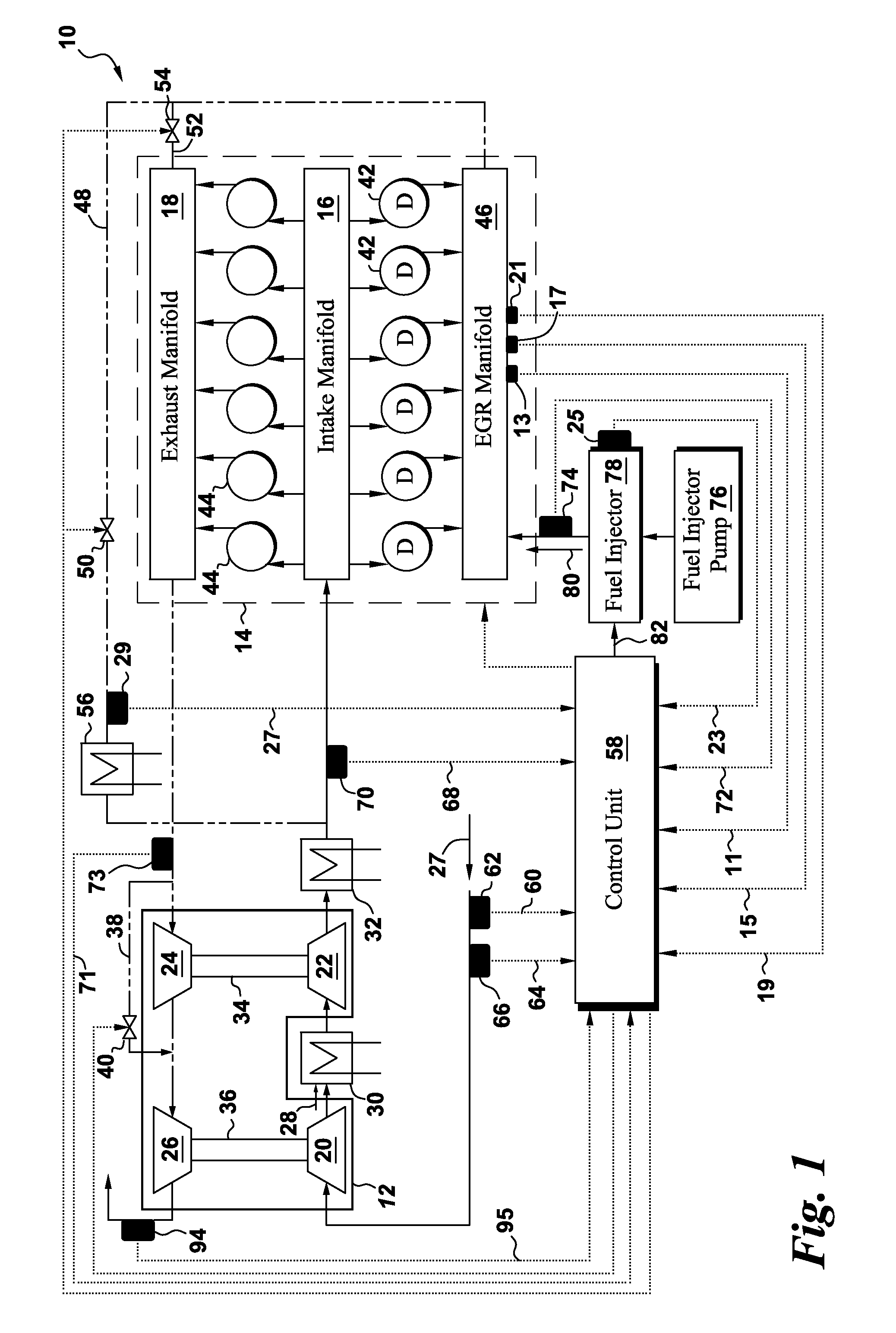
[0017]Referring to FIG. 1, a turbocharged unit 10 having exhaust emission and specific fuel consumption (SFC) control features, is illustrated in accordance with certain embodiments of the present invention. The turbocharged unit 10 includes a turbo-charger 12 and a compression-ignition engine, e.g., a diesel engine 14. A motor-generator unit (not shown) may be mechanically coupled to the diesel engine 14. As discussed in further detail below, emb...


PUM


Abstract

A method includes controlling an engine speed based on: intake manifold air temperature and/or intake manifold pressure one, or more, of the following data parameters: an engine load as a function of a fuel level, a fuel injecting timing, an intake oxygen concentration, a constituent concentration from the exhaust gas flow, an engine power, and an engine torque. The method also recirculates a portion of the exhaust gas flow to the combustion cylinders of the engine via a recirculation channel, as a function of intake manifold temperature and/or intake manifold pressure at which the engine is operated. An engine system, other methods, and a non-transitory computer readable medium encoded with a program, to enable a processor-based control unit to control aspects of the engine are also disclosed.

Description


Claims


Application Information

Patent Timeline
Owner GE GLOBAL SOURCING LLC
Why Eureka
Try Eureka