
Ultra-Miniature Multi-Hole Flow Angle Probes

a flow angle and ultra-miniature technology, applied in the field of multi-hole pressure probes, can solve the problems of reducing the number of measurements, restricting the time response to several seconds or longer, and the absolute transducer in the probe to perform the measurement of very small changes in pressur

Active Publication Date: 2016-01-14
KULITE SEMICON PRODS
View PDF15 Cites 10 Cited by
  • Summary
  • Abstract
  • Description
  • Claims
  • Application Information

AI Technical Summary

Benefits of technology

This patent relates to small, multi-hole flow angle probes with integrated transducers for measuring environmental conditions. The probes have a housing with two oblique sides and two apertures, with each aperture on an oblique side. The transducers measure the environmental conditions at their respective apertures and output signals. The probes have a width of less than five-tenths of an inch and may be used in various applications such as chemical analysis and biological research. The technical effects of this patent are the design of ultra-miniature flow angle probes that enable the measurement of environmental conditions with high accuracy and precision.

Problems solved by technology

However, a reduction in probe size typically leads to reducing the number of measurements, which may result in fewer flow variables.
Furthermore, to enable fabrication of small probes, the static pressure ports on these steady state probes are usually connected to remote pressure transducers over long lengths of small diameter tubing, which may restrict their time response to several seconds or longer.
However, the use of absolute transducers in the probes to perform measurements of very small changes in pressure may introduce errors.
Such errors may be associated with the use of separate high pressure absolute transducers for measuring very small changes in pressure riding on top of the stagnation pressure, which is a typical occurrence with low speed turbo-machinery.

Method used


Image

  • Ultra-Miniature Multi-Hole Flow Angle Probes
  • Ultra-Miniature Multi-Hole Flow Angle Probes
  • Ultra-Miniature Multi-Hole Flow Angle Probes

Examples


Embodiment Construction

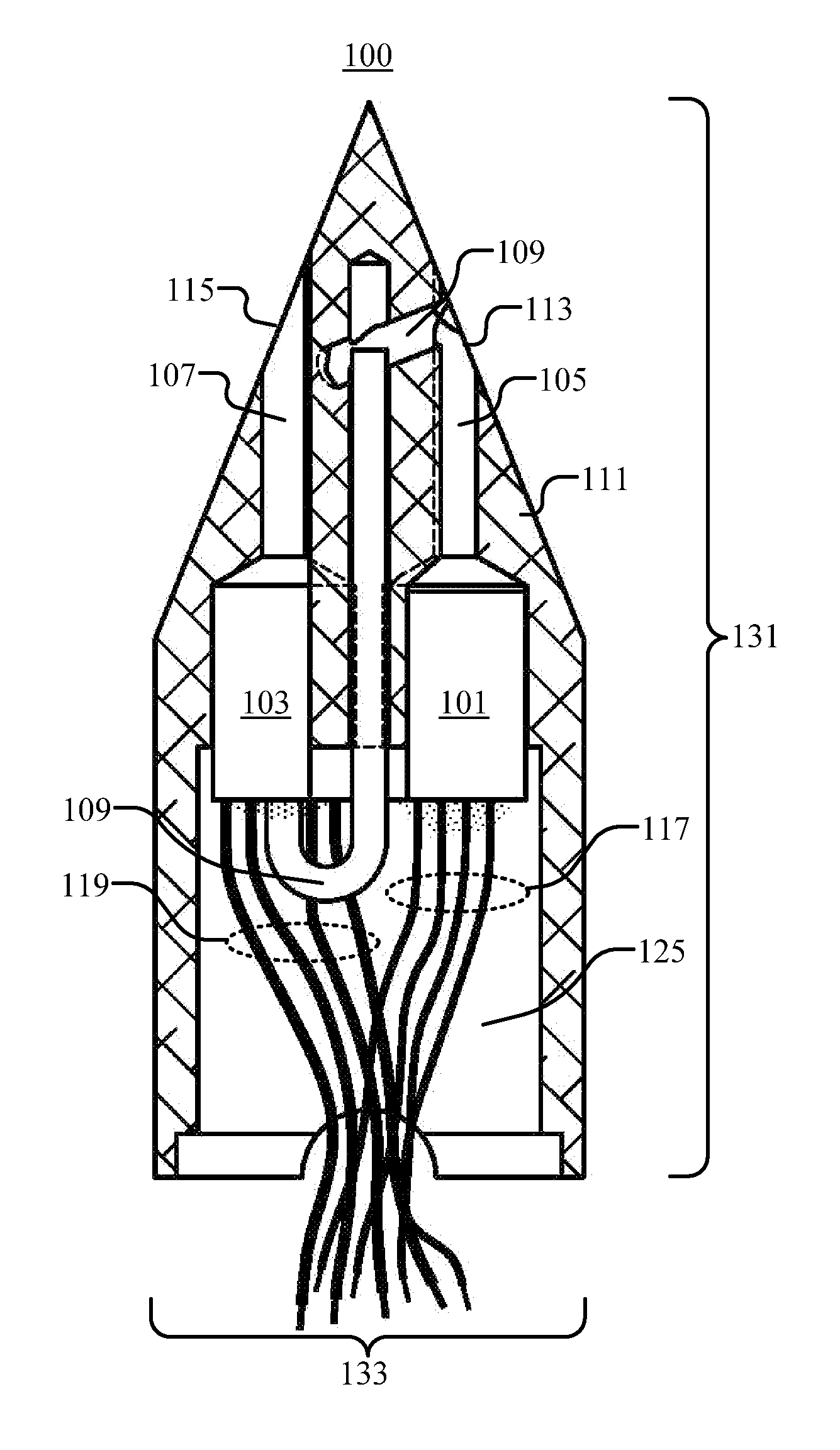
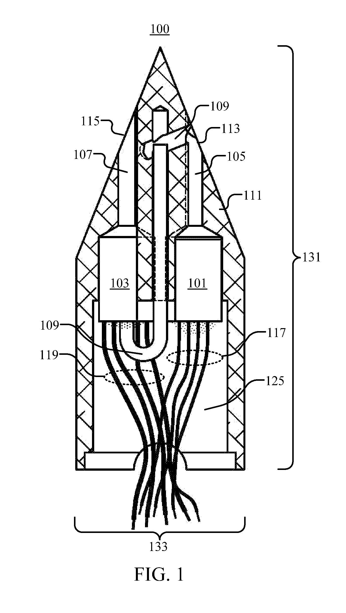
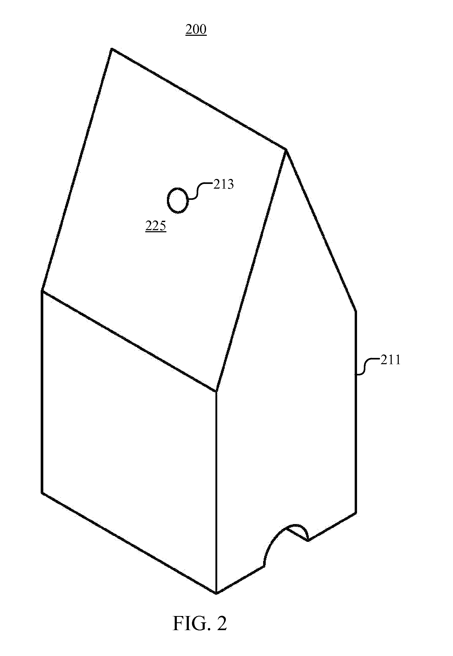
[0018]The following detailed description is merely illustrative in nature and is not intended to limit the present disclosure, or the application and uses of the present disclosure. Furthermore, there is no intention to be bound by any expressed or implied theory presented in the preceding field of use, background, or summary of the disclosure or the following detailed description. The present disclosure provides various examples, embodiments and the like, which may be described herein in terms of functional or logical block elements. Various techniques described herein may be used for ultra-miniature, multi-hole flow angle probes. The various aspects described herein are presented as methods, devices (or apparatus), and systems that may include a number of components, elements, members, modules, nodes, peripherals, or the like. Further, these methods, devices, and systems may include or not include additional components, elements, members, modules, nodes, peripherals, or the like.

[...


PUM

PropertyMeasurementUnit
lengthaaaaaaaaaa
heightaaaaaaaaaa
heightaaaaaaaaaa

Abstract

This disclosure provides example methods, devices, and systems for an ultra-miniature, multi-hole flow angle probe. The construction, packaging of a multitude of absolute and or differential pressure transducers or sensors are invented for the purpose of providing highly accurate measurement of flow properties, flow angle in particular. The unique placement of sensors leads to further miniaturization relative to current state of the art. Further the use of closely coupled, differential transducer or transducers achieves higher accuracy measurement of small pressure variations coupled with large mean or average baseline pressures, as is demanded in modern aerodynamic or turbo-machinery devices. The use and installation of ultra-miniature sensors insider the device invented herein achieves higher frequency response than allowable via previous state of the part.

Description

TECHNICAL FIELD[0001]This invention relates to multi-hole pressure probes and more particularly to ultra-miniature, multi-hole flow angle probes.BACKGROUND[0002]The use of multi-hole pressure probes is a longstanding approach for measuring flow angles, stagnation and static pressures. Orthogonal flow angles as well as stagnation and static pressure may all be deduced from pressures measured at, for instance, several well chosen locations on the probe. Since the Mach number is a unique function of the ratio of stagnation to static pressure, the Mach number may also be derived from the pressures measured by a multi-hole pressure probe. A larger number of measurement locations on a multi-hole pressure probe may generally improve measurement accuracy but in exchange for an increased probe size. Probe size may be important for reducing disturbances in the flow field. However, a reduction in probe size typically leads to reducing the number of measurements, which may result in fewer flow ...

Claims


Application Information

Patent Timeline
Patent Type & Authority Applications(United States)
IPC IPC(8): G01L9/00G01L9/06
CPCG01L9/0054G01L9/06G01L19/0038G01F1/46G01P5/16G01P5/165G01P13/025
Inventor NED, ALEXANDER A.SHANG, TONGHUOGOODMAN, SCOTTCARTER, STEVEVANDEWEERT, JOSEPH R.
Owner KULITE SEMICON PRODS
Learn More