Current source for voltage regulator and voltage regulator thereof

a voltage regulator and current source technology, applied in the direction of electric variable regulation, process and machine control, instruments, etc., can solve the problems of reducing response speed, increasing the cost of the voltage regulator, and reducing the response speed, so as to achieve stable output voltage, stabilize output voltage, and quickly adjust output current magnitude

Active Publication Date: 2016-01-14
NOVATEK MICROELECTRONICS CORP
View PDF2 Cites 5 Cited by
  • Summary
  • Abstract
  • Description
  • Claims
  • Application Information

AI Technical Summary

Benefits of technology

[0007]It is therefore an objective of the present invention to provide a current source and voltage regulator capable of quickly adjusting output currents, to quickly adjust the magnitude of the output current when a load terminal requires a large instant current, and thereby stabilize the output voltage while preventing the output voltage from being pulled down by the load current and causing malfunctions.

Problems solved by technology

In order to allow the voltage regulator to support large current variations, a large voltage regulation capacitor should be applied, which increases the cost of the voltage regulator and also reduces the response speed.
This leads to a quick fall in the source voltage of the NMOS and failure to achieve a stable output voltage.
These types of voltage regulator require a more complex circuit design, which increases the cost and results in redundant power consumption.
Furthermore, the instant current source is enabled after the output voltage has an evident fall, which limits the regulation effect in the output voltage.
Since these circuit structures have two comparators controlled by two control loops, stability problems may easily occur.
As technology processes progress, the density of digital circuits becomes higher and their associated functionalities become more powerful, which results in larger instant currents.
Modern voltage regulators without voltage regulation capacitors are not adequate for the required response speed.
Even voltage regulators including voltage regulation capacitors are unable to provide a satisfactory voltage regulation effect due to parasitic resistances inside or outside the chip when the current requirement in the load terminal keeps increasing.

Method used


Image

  • Current source for voltage regulator and voltage regulator thereof
  • Current source for voltage regulator and voltage regulator thereof
  • Current source for voltage regulator and voltage regulator thereof

Examples


Embodiment Construction

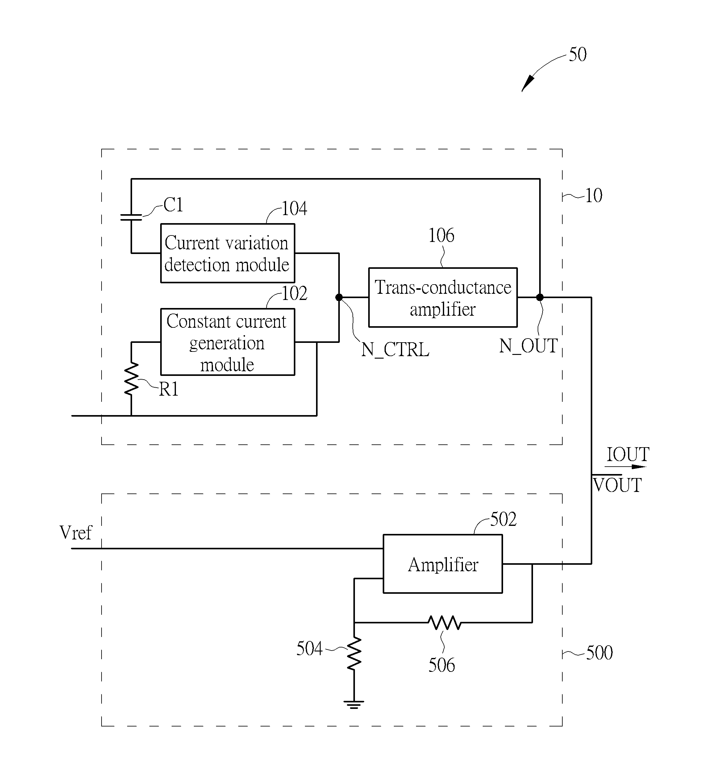
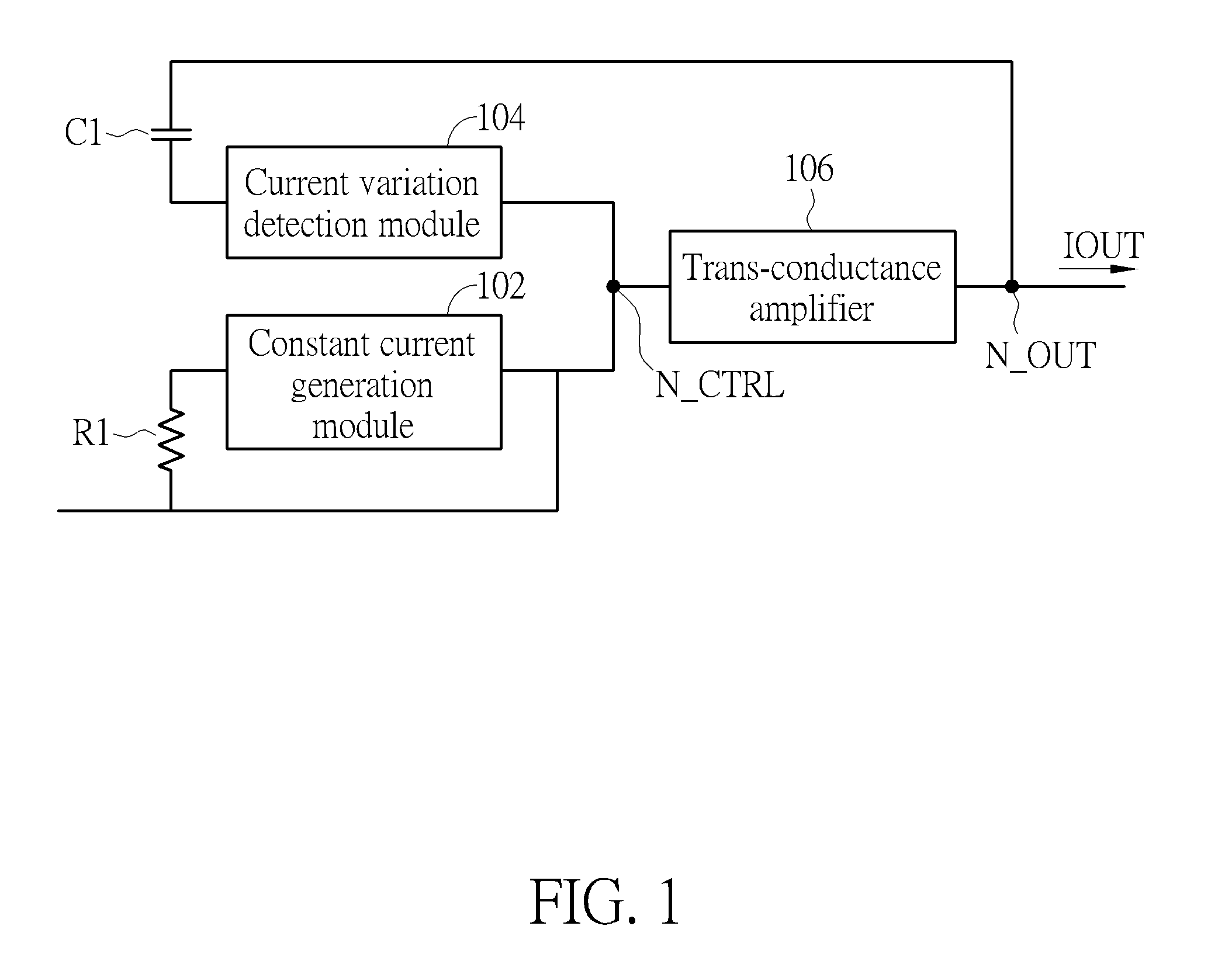
[0021]FIG. 1 is a schematic diagram of a current source 10 according to an embodiment of the present invention. The current source 10 includes a constant current generation module 102, a capacitor C1, a current variation detection module 104 and a trans-conductance amplifier 106. The constant current generation module 102, coupled to a control node N_CTRL, is utilized for generating a predefined current flowing through the control node N_CTRL in order to determine the voltage of the control node N_CTRL. The predefined current is mainly utilized for adjusting the bias voltage of the control node N_CTRL, and may be a smaller current to prevent unnecessary power consumption. The capacitor C1 is coupled between an output terminal N_OUT of the current source 10 and the current variation detection module 104. The current variation detection module 104, coupled between the control node N_CTRL and the capacitor C1, may generate a variation on the voltage of the control node N_CTRL via the c...


PUM


Abstract

A current source for quickly adjusting an output current includes a constant current generation module, coupled to a control node, for generating a predefined current flowing through the control node in order to determine a voltage of the control node; a capacitor, coupled to an output terminal of the current source; a current variation detection module, coupled between the control node and the capacitor, for generating a variation on the voltage of the control node via the capacitor when the output terminal of the current source receives an instant current variation; and a trans-conductance amplifier, coupled between the control node and the output terminal, for changing a magnitude of the output current of the output terminal when the variation on the voltage of the control node is generated.

Description

BACKGROUND OF THE INVENTION[0001]1. Field of the Invention[0002]The present invention relates to a current source for a voltage regulator, and more particularly, to a current source capable of quickly adjusting an output current of a voltage regulator, and a voltage regulator thereof.[0003]2. Description of the Prior Art[0004]A voltage regulator utilizes a feedback circuit to maintain its desired output voltage. A voltage regulation capacitor is disposed in the output terminal of the voltage regulator to assist in regulation capability of the voltage regulator. The voltage regulation capacitor is responsible for converting pre-stored charge into a driving current that can be provided to the load driven by the voltage regulator when its current requirement changes rapidly. This can maintain stability in the output voltage of the output terminal. In order to allow the voltage regulator to support large current variations, a large voltage regulation capacitor should be applied, which i...

Claims


Application Information

Patent Timeline
Patent Type & Authority Applications(United States)
IPC IPC(8): G05F1/625
CPCG05F1/625G05F1/565
Inventor HU, MIN-HUNGHUANG, CHIU-HUANGWU, CHEN-TSUNGHUANG, CHUN-WEISU, PIN-HAN
Owner NOVATEK MICROELECTRONICS CORP
Why Eureka
Try Eureka