Flat cable reeling device

Active Publication Date: 2016-01-14
YAZAKI CORP
View PDF4 Cites 9 Cited by
  • Summary
  • Abstract
  • Description
  • Claims
  • Application Information

AI Technical Summary

Benefits of technology

[0012]According to the one aspect of the present invention, the rotating table is integrally provided with the disk-like table main body and the plurality of guiding portions formed to project from the upper surface of the table main body, the table main body is provided with the plurality of rollers adapted to reel the flat cable from the outside of the case arranged along the circumferential direction of the table main body, and the plurality of guiding portions are provided at the respective positions at which the respective rollers are arranged, rotatively support the respective rollers, and guide the respective rollers to be slidable in the radial direction of the rotating table. Accordingly, the respective rollers are guided to be slidable by the plurality of guiding portions formed to project from the upper surface of the table main body, this can dispense with the retaining groove formed in the recessed shape from the upper surface of the rotor in the conventional sliding mechanism, and size reduction of the flat cable reeling device in an up-down direction can be achieved as much as the omission of the retaining groove. Also, the rotating table integrally includes the disk-like table main body and the plurality of guiding portions formed to project from the upper surface of the table main body, and this means the sliding mechanism of the roller is achieved by two members: the rotating table and the roller. Thus, the number of parts can be reduced further than in the conventional reeling mechanism, in which the sliding mechanism is achieved by three members: the roller main body, the shaft portion, and the rotor, and assembling operability can be improved. Also, omitting t

Problems solved by technology

However, since the aforementioned reeling structure is configured so that the lower end portion of the boss may be retained at the retaining groove formed in the recessed shape from the upper surface of the rotor 103 to cause the boss to slide, there is a problem in which the reeling structure is larger

Method used


Image

  • Flat cable reeling device
  • Flat cable reeling device
  • Flat cable reeling device

Examples


Embodiment Construction

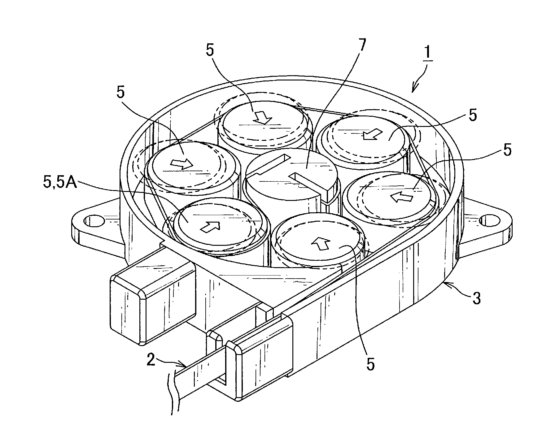
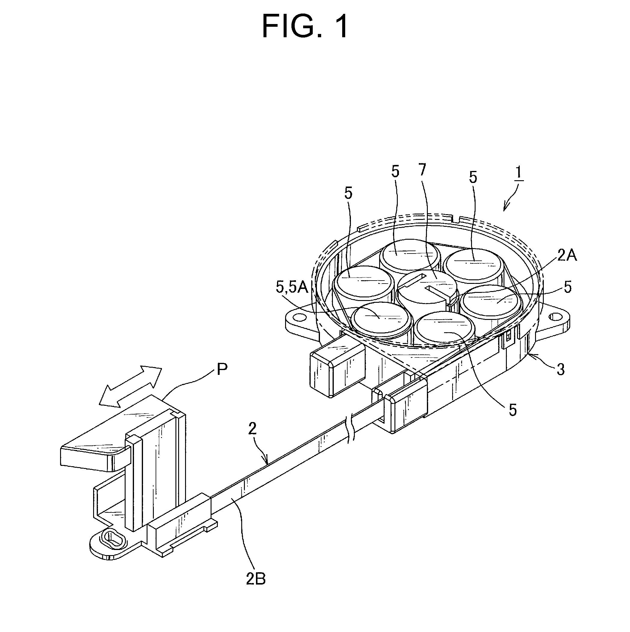
[0022]Hereinbelow, an exemplary embodiment of a flat cable reeling device according to the present invention will be described with reference to FIGS. 1 to 5. A flat cable reeling device 1 reels a flat cable 2 routed between a sliding seat slidably provided to a floor of a vehicle or the like and the vehicle, for example. A first end of the flat cable 2 is connected with a connector or the like provided on a side of the floor while a second end side of the flat cable 2 is guided to a protector P guided along a sliding rail and is connected with a connector or the like on a side of the sliding seat via this protector P. This flat cable reeling device 1 is provided close to the sliding rail. The flat cable reeling device 1 reels the flat cable 2 along with approaching movement of the protector P and unreels the flat cable 2 along with separating movement of the protector P to prevent slack of the flat cable 2 between the reeling device 1 and the protector P, thus to prevent the flat c...


PUM


Abstract

An object of the present invention is to provide a flat cable reeling device reducing a size. A flat cable reeling device includes a case housing a flat cable, a center shaft provided in the case and fixing a first end side of the flat cable, a rotating table rotatively provided, centering on the center shaft, and a biasing means biasing the rotating table in a reeling direction of the flat cable. The rotating table is provided with a plurality of rollers adapted to reel the flat cable from an outside of the case along a circumferential direction of the rotating table. The rotating table is integrally provided with a disk-like table main body and a plurality of guiding portions formed to project from an upper surface of the table main body, and the plurality of guiding portions rotatively support the respective rollers and guide the respective rollers to be slidable in a radial direction of the rotating table.

Description

TECHNICAL FIELD[0001]The present invention relates to a flat cable reeling device reeling a first end side of a flat cable and unreeling a second end side thereof.BACKGROUND ART[0002]For example, in a car or the like, a sliding seat, a sliding door, and the like slidably provided to a vehicle are used. The sliding seat is provided with electronic components such as a seating sensor detecting whether or not an occupant is seated and a seat belt sensor detecting whether or not a seat belt is fastened, and the sliding door is provided with electronic components such as a driving motor adapted to drive a door window for opening / closing and a door courtesy lamp adapted to illuminate the occupant's feet when a door is opened. For this reason, in the vehicle provided with a sliding body such as the sliding seat and the sliding door, various wire routing devices or power feeding devices routing wires between the vehicle and the sliding body are used to connect the electronic components on t...

Claims


Application Information

Patent Timeline
IPC IPC(8): H02G11/02B65H75/44B65H75/48
CPCH02G11/02B65H75/4471B65H75/48
Inventor KATSURAMAKI, TAKAHIKOHAMADA, RYO
Owner YAZAKI CORP
Why Eureka
Try Eureka