Multi-terminal DC power systems employing autonomous local control methods

a dc power system and multi-terminal technology, applied in the direction of dc source parallel operation, wind energy generation, electric power transfer ac network, etc., can solve the problems of increasing control complexity exponentially with the number of terminals, and it is more difficult to implement such control for pwm-based systems, so as to facilitate formation and operation of multi-terminal dc systems, enhance transient stability, avoid possible conflict in steady-state operation

Active Publication Date: 2016-01-14
RENESSELAER POLYTECHNIC INST
View PDF3 Cites 5 Cited by
  • Summary
  • Abstract
  • Description
  • Claims
  • Application Information

AI Technical Summary

Benefits of technology

This patent describes how to create multiple machines that work together without one machine controlling them all. Instead, each machine has its own method for making decisions based on what it's seeing. A coordinating network makes sure these decision makers don't collide with each other too often, but they are always able to communicate when needed. Overall, this allows for more efficient and flexible networks made up of many small machines working together seamlessly.

Problems solved by technology

This patent describes a method for controlling a multi-terminal DC power system, specifically using both lines of control and individual control modules for each source and load terminal. The technical problem addressed by the patent is how to efficiently manage these complex systems without increasing control complexity and delay when communicating data amongst various components.

Method used


Image

  • Multi-terminal DC power systems employing autonomous local control methods
  • Multi-terminal DC power systems employing autonomous local control methods
  • Multi-terminal DC power systems employing autonomous local control methods

Examples


Embodiment Construction

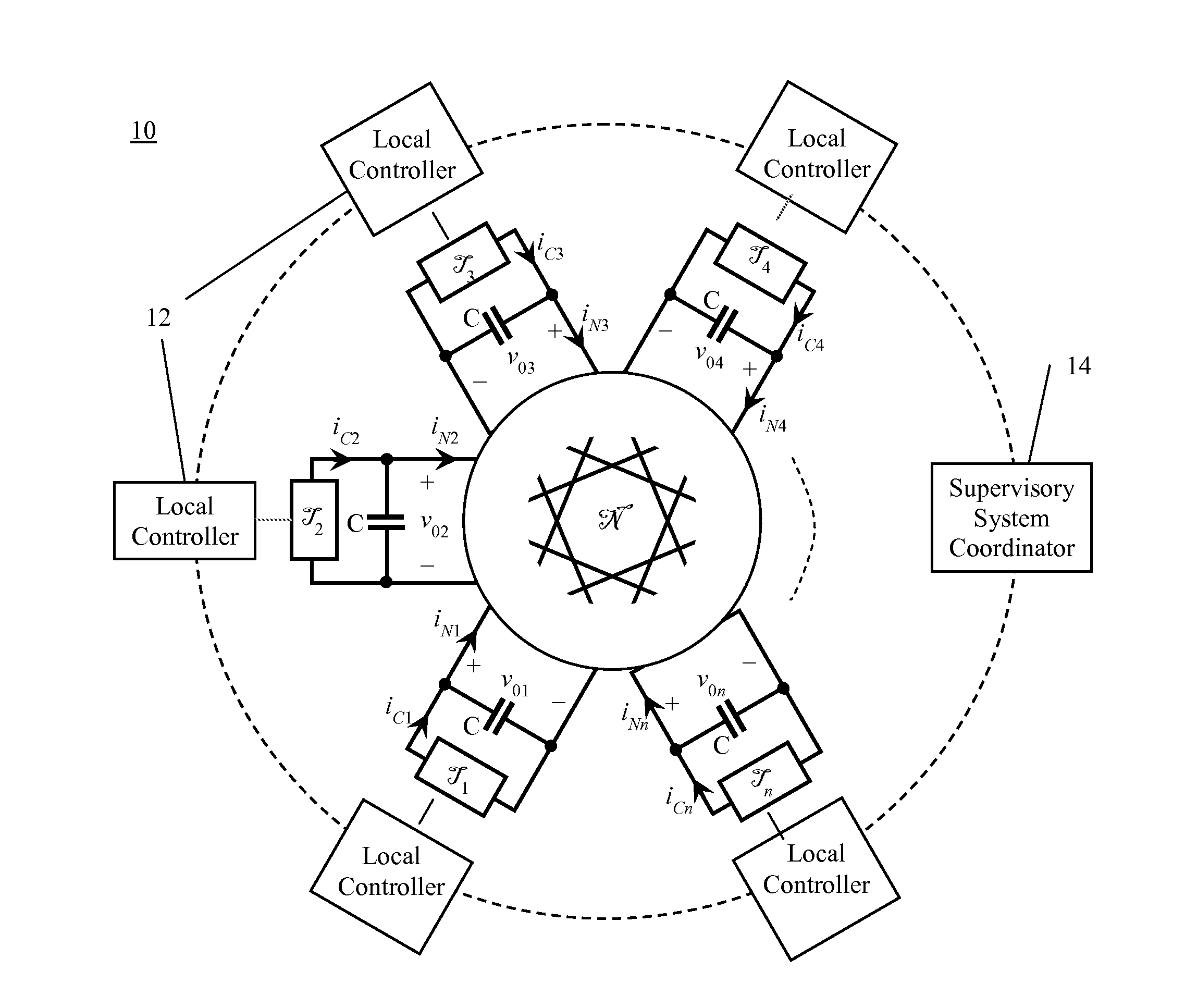
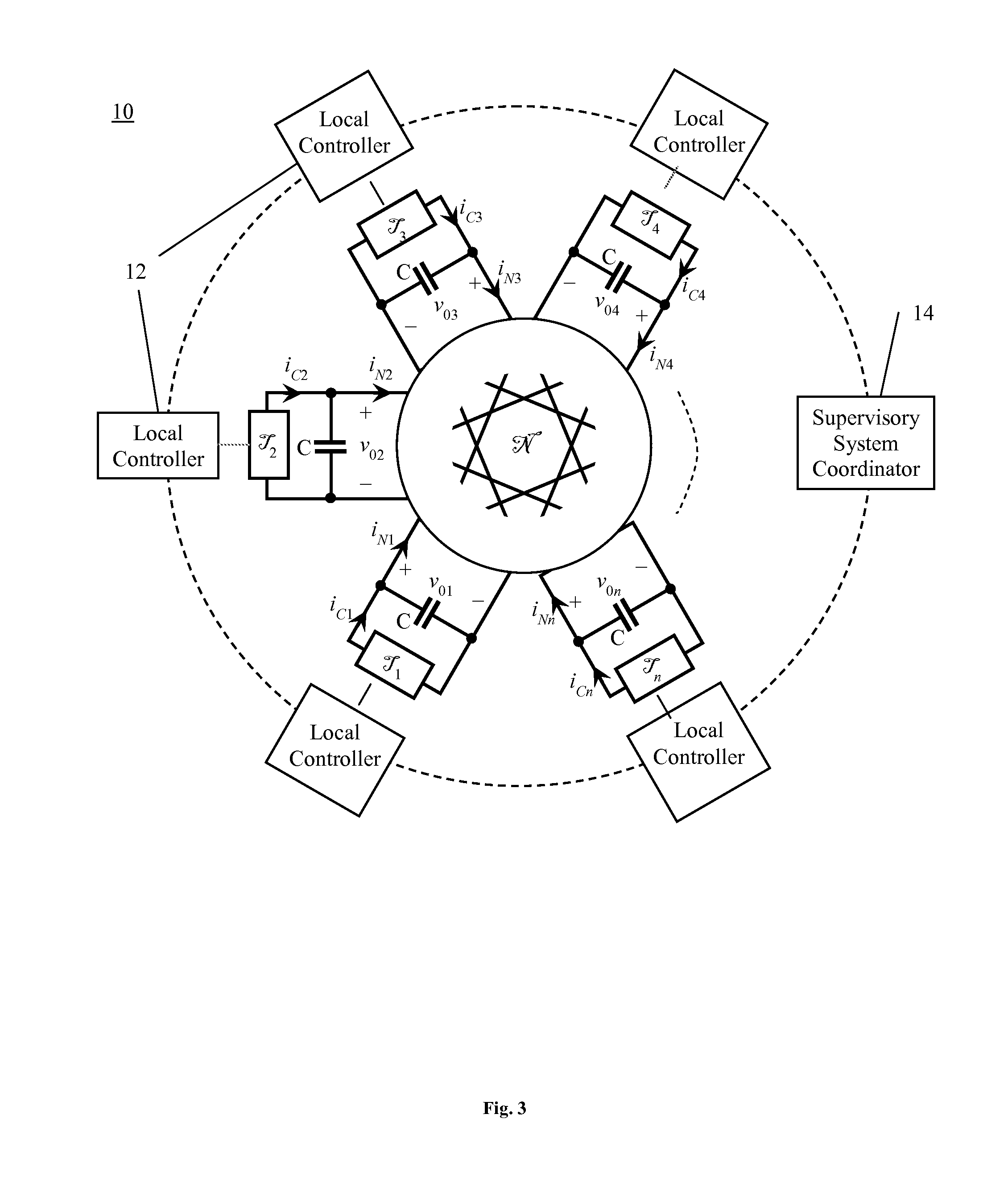
[0051]According to the present invention, local direct control of converter-side voltages and currents provides a new advantageous way to operate multi-terminal DC power systems. Such control requires only local variables that are directly measurable at each terminal. This allows each terminal control to be designed and implemented independently from other terminals. In this manner, different terminals can operate antonomously while system stability is ensured by the selection of appropriate control modes.

[0052]Supervisory control coordination requiring only occasional or intermittent exchange of low-bandwidth signals may be incorporated at the system level to avoid possible conflict in steady-state operation and to enhance transient stability. The combination of autonomous local control find simple supervisory system coordination greatly simplifies system design and improves system reliability, as well as tolerance to interrupts and faults in communication. The approaches of the pr...


PUM


Abstract

A multi-terminal DC power system includes: a DC network connecting together multiple terminals. Each terminal is represented by one of: a voltage source converter having a capacitor at an interface to the DC network, wherein a difference between a converter-side current and a network-side current charges the capacitor, and a current source converter having an inductor at an interface to the DC network, wherein a difference between a converter-side voltage and a network-side voltage drives current through the inductor. A local controller for each terminal directly controls the converter-side current of each voltage source controller and the converter-side voltage of each current source converter, independent of the terminals, leaving network-side currents and voltages to be determined by the network, resulting in simplified terminal control and avoidance of the need for high-speed communication among all terminals at all times.

Description


Claims


Application Information

Patent Timeline
Owner RENESSELAER POLYTECHNIC INST
Why Eureka
Try Eureka