Control apparatus, power supply control apparatus, charge control method, charge control apparatus, and power supply apparatus for vehicles

a technology for controlling apparatus and power supply, which is applied in the direction of battery/fuel cell control arrangement, secondary cell servicing/maintenance, capacitor propulsion, etc., can solve the problems of small electric power that the storage battery can store, and it takes a long time to charge the storage battery, so as to reduce the supply voltage and charge quickly

Inactive Publication Date: 2016-01-21
AUTONETWORKS TECH LTD +2
View PDF0 Cites 49 Cited by
  • Summary
  • Abstract
  • Description
  • Claims
  • Application Information

AI Technical Summary

Benefits of technology

[0077]With the control apparatus according to embodiments of the present application, charging to the storage battery is appropriately switched from charging via the first charge channel to charging via the second charge channel, and therefore the storage battery can be quickly charged and a large amount of electric power can be stored in the storage battery.
[0078]The power supply control apparatus according to embodiments of the present application is capable of efficiently charging a first storage battery and a second storage battery each with a different charge voltage, and allows the electric power stored in each of the first storage battery and the second storage battery to be consumed efficiently.
[0079]The charge control method according to embodiments of the present application achieves a charge control method that is unlikely to cause a decrease in supply voltage to an electric load w

Problems solved by technology

For this reason, the power supply apparatus described in JP 2012-240487A has the problem that it takes a long time to charge the storage battery.
Also, regarding the storage battery described in JP 2012-240487A, there is no possibility

Method used


Image

  • Control apparatus, power supply control apparatus, charge control method, charge control apparatus, and power supply apparatus for vehicles
  • Control apparatus, power supply control apparatus, charge control method, charge control apparatus, and power supply apparatus for vehicles
  • Control apparatus, power supply control apparatus, charge control method, charge control apparatus, and power supply apparatus for vehicles

Examples


embodiment 1

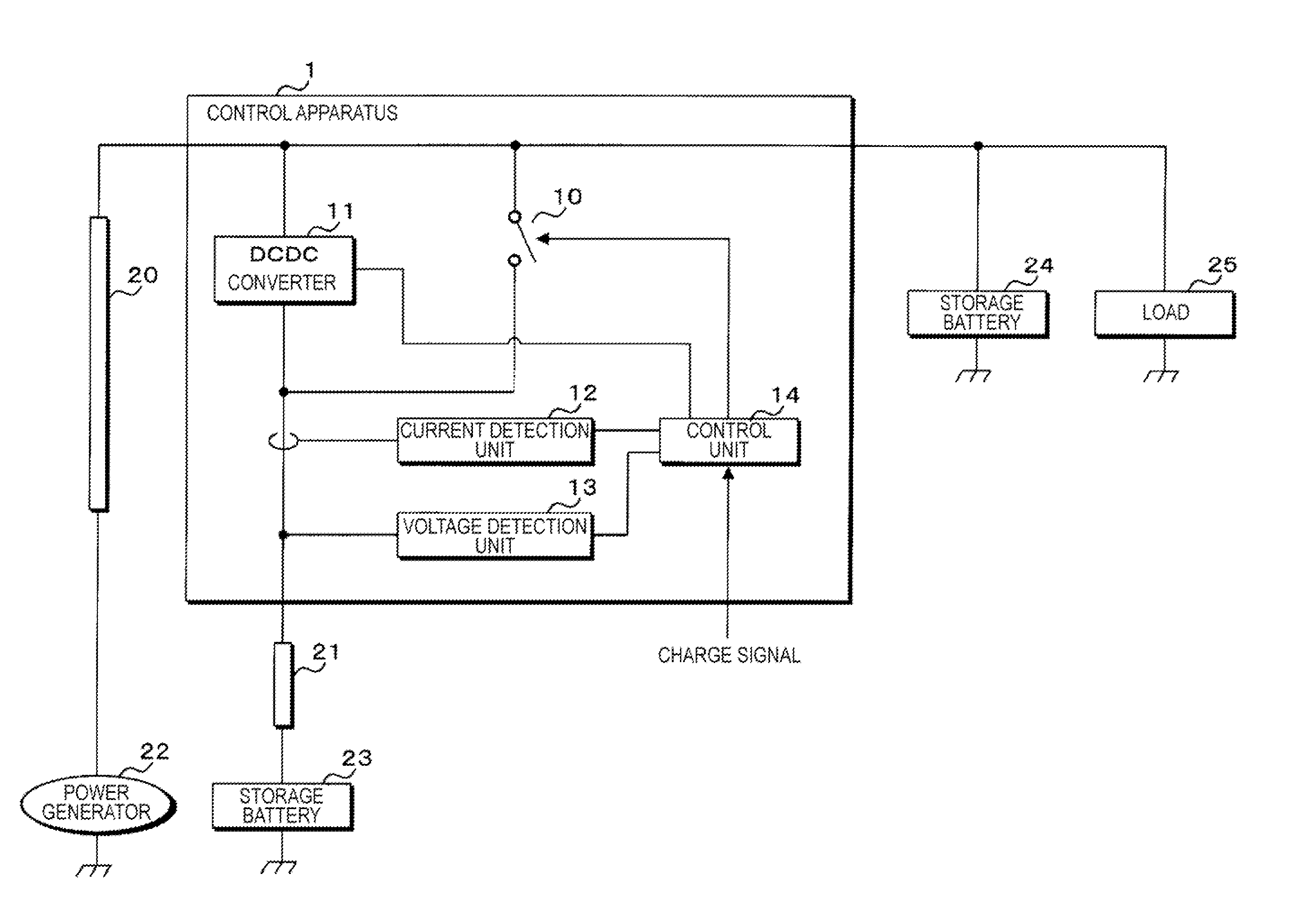
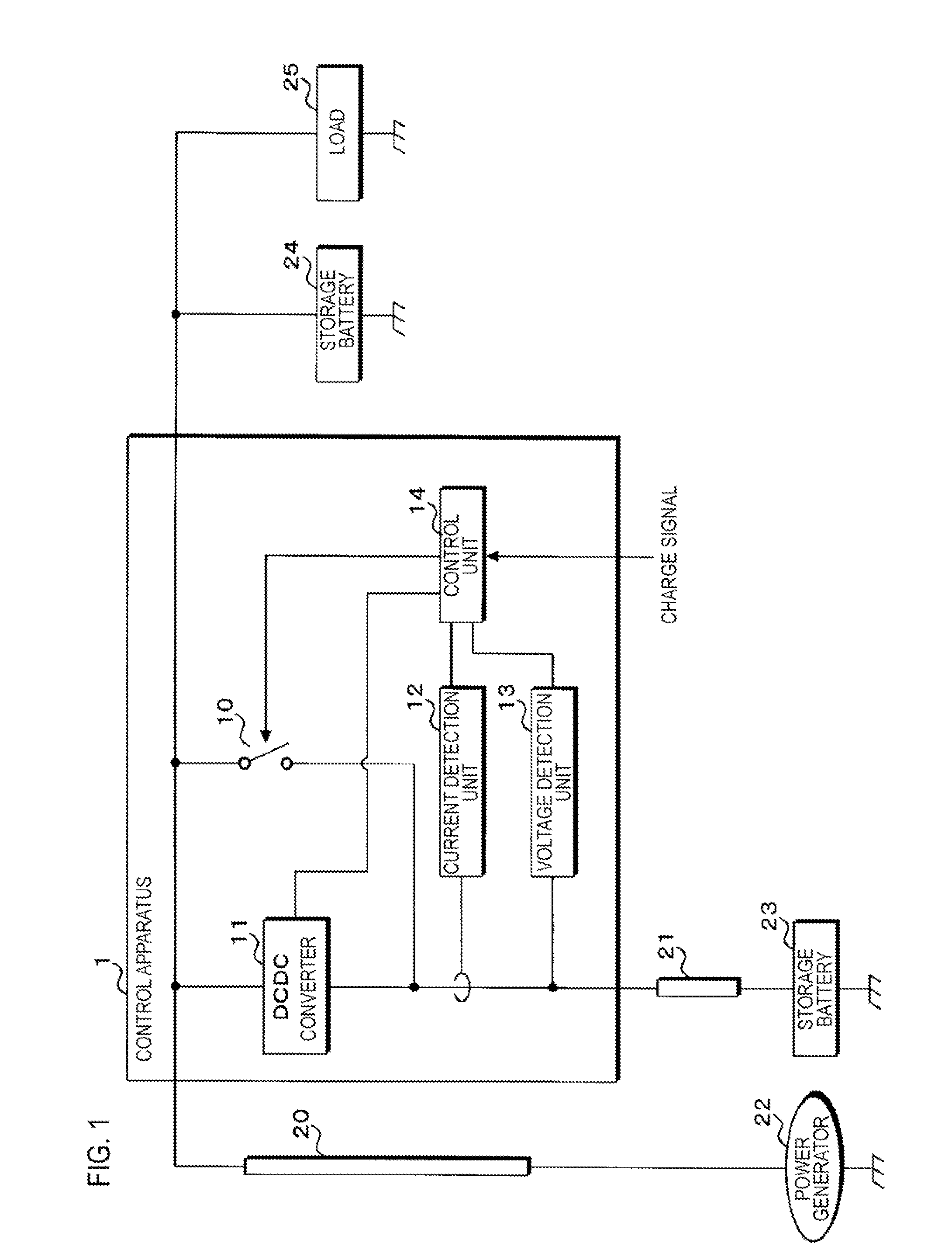
[0100]FIG. 1 is a block diagram showing a configuration of a power supply apparatus in Embodiment 1. This power supply apparatus is suitably mounted on a vehicle, and includes a control apparatus 1, electric wires 20 and 21, a power generator 22, storage batteries 23 and 24, and a load 25. The control apparatus 1 is connected between one end of the electric wire 20 and one end of the electric wire 21, the other end of the electric wire 20 is connected to one end of the power generator 22, and the other end of the electric wire 21 is connected to the positive terminal of the storage battery 23. The control apparatus 1 is connected to one end of the storage battery 24 and one end of the load 25, in addition to being connected to the electric wires 20 and 21. The other end of the power generator 22, the other end of the load 25, and the respective negative terminals of the storage batteries 23 and 24 are grounded.

[0101]The power generator 22 generates electric power by operating in con...

embodiment 2

[0141]FIG. 4 is a block diagram showing a configuration of a power supply apparatus in Embodiment 2. This power supply apparatus includes a control apparatus 3 instead of the control apparatus 1 within the power supply apparatus in Embodiment 1. The power supply apparatus in Embodiment 1 is configured such that the charge current value to the storage battery 23 is maintained at the upper limit value. In contrast, the power supply apparatus in Embodiment 2 is configured such that the voltage across the two ends of the electric wire 21 is maintained at a constant value.

[0142]The following describes the power supply apparatus in Embodiment 2 in terms of the differences from the power supply apparatus in Embodiment 1. The components that Embodiment 2 has in common with Embodiment 1 are given the same reference signs, and the detailed description thereof is omitted.

[0143]The power supply apparatus in Embodiment 2 is suitably mounted on a vehicle as with the power supply apparatus in Embo...

embodiment 3

[0172]FIG. 6 is a block diagram showing a configuration of Embodiment 3 of a power supply system according to the present application. This power supply system 31 is suitably mounted on a vehicle, and includes an alternator 41, storage batteries 42 and 43, a load 44, a starter 45, and a power supply control apparatus 46. The power supply control apparatus 46 has terminals T1, T2, and T3.

[0173]To the terminals T1, T2, and T3 of the power supply control apparatus 46, the positive terminal of the alternator 41, the positive terminal of the storage battery 42, and the positive terminal of the storage battery 43 are detachably connected, respectively. Furthermore, to the positive terminal of the storage battery 43, one end of the load 44 and one end of the starter 45 are connected. The respective negative terminals of the alternator 41 and the storage batteries 42 and 43, the other end of the load 44, and the other end of the starter 45 are grounded.

[0174]The alternator 41 generates rege...


PUM


Abstract

A control apparatus charging a storage battery is provided. A control apparatus controls charging from a power generator to a storage battery. A switch is provided on a first charge channel via which the power generator charges the storage battery, and a DCDC converter is provided on a second charge channel via which the power generator charges the storage battery. The DCDC converter steps up a voltage generated by the power generator, and applies the stepped-up voltage to the storage battery via an electric wire. A controller controls the switch and the DCDC converter such that, when a charge current value detected by an electric current detector becomes smaller than a predetermined value under a condition where the storage battery is being charged via the first charge channel, charging to the storage battery is switched to charging via the second charge channel.

Description

CROSS-REFERENCE TO RELATED APPLICATIONS[0001]This application is a National Stage application of International Application No. PCT / JP2014 / 057962, filed on Mar. 24, 2014, and claims priority to Japanese Patent Application No. 2013-077983, filed on Apr. 3, 2013, Japanese Patent Application No. 2013-126888, filed on Jun. 17, 2013, and Japanese Patent Application No. 2013-126889, filed on Jun. 17, 2013, the disclosures of which are incorporated herein by reference in their entireties.TECHNICAL FIELD[0002]Embodiments of the present application relate: a control apparatus that controls charging that is performed by supplying electric power generated by a power generator to a storage battery; a power supply control apparatus that controls power supply from a power generator to a storage battery and a load and power supply from the storage battery to the load; a charge control method for a charge control apparatus that includes a voltage conversion means for converting, as needed, a voltage...

Claims


Application Information

Patent Timeline
IPC IPC(8): B60L11/18B60L7/10B60L50/16H02J7/00H02M3/02
CPCB60L11/1861B60L7/10H02M3/02B60L11/1859H02J7/007B60L11/1868H01M10/44H01M10/48B60L2240/44B60L1/003B60L1/14B60L15/007B60L15/2009B60L2240/12B60L2240/421B60L2240/423B60L2240/427B60L2240/429B60L2240/529B60L2240/547B60L2240/549B60L2240/527B60L7/14B60L2210/14B60L2210/30B60L2210/40H02J7/1415H02J7/1423H02J7/1438H02J7/1492Y02T10/70B60L50/40B60L50/16B60L58/14B60L58/20H02J7/342H02J2310/48Y02T10/64Y02T10/72Y02T10/7072Y02E60/10B60L3/0046B60L58/12
Inventor YASUNORI, HIROMICHITANIGUCHI, TOMOHIRO
Owner AUTONETWORKS TECH LTD
Why Eureka
Try Eureka