
Mechanism for passenger flow management

a passenger flow and passenger technology, applied in the field of passenger flow management, can solve the problems of large number of base stations, increased labor intensity, and inability to meet the needs of passengers, so as to reduce inconvenience and shorten travel time

Inactive Publication Date: 2016-01-21
KONE CORP
View PDF0 Cites 12 Cited by
  • Summary
  • Abstract
  • Description
  • Claims
  • Application Information

AI Technical Summary

Benefits of technology

The invention can help transportation devices be optimized based on actual passenger flows, instead of estimates, to provide the best possible capacity for every traffic condition. This can result in shorter travel times and less inconvenience for passengers. Additionally, instead of only optimizing capacity, the invention can also determine the quality of service needed to meet the passenger flow demand. This way, some transportation devices can be disabled for energy saving when not needed.

Problems solved by technology

The problem of the traditional implementations is that the traffic hours are only estimates and might be incorrect.
The problem of this approach is that these gates are typically only in the lobby or other entrances.
Similar problems occur when public events, for example concerts or sport events, are arranged.
Public transportation operator may be willing to provide additional trains or busses for serving the crowd but they do not have the exact information when the event is over.
The problem of the solution disclosed above is the price of additional identification points, such as Bluetooth base stations.
As the range of such base station is small a very large number of base stations may be needed.
Without these investments there is not enough data of passenger flows and transportation devices cannot be controlled by using passenger flow information.
When the whole capacity is not needed some of the transportation devices may be disabled for energy saving.

Method used


Image

  • Mechanism for passenger flow management
  • Mechanism for passenger flow management
  • Mechanism for passenger flow management

Examples


Embodiment Construction

[0020]Reference will now be made in detail to the embodiments of the present invention, examples of which are illustrated in the accompanying drawings.

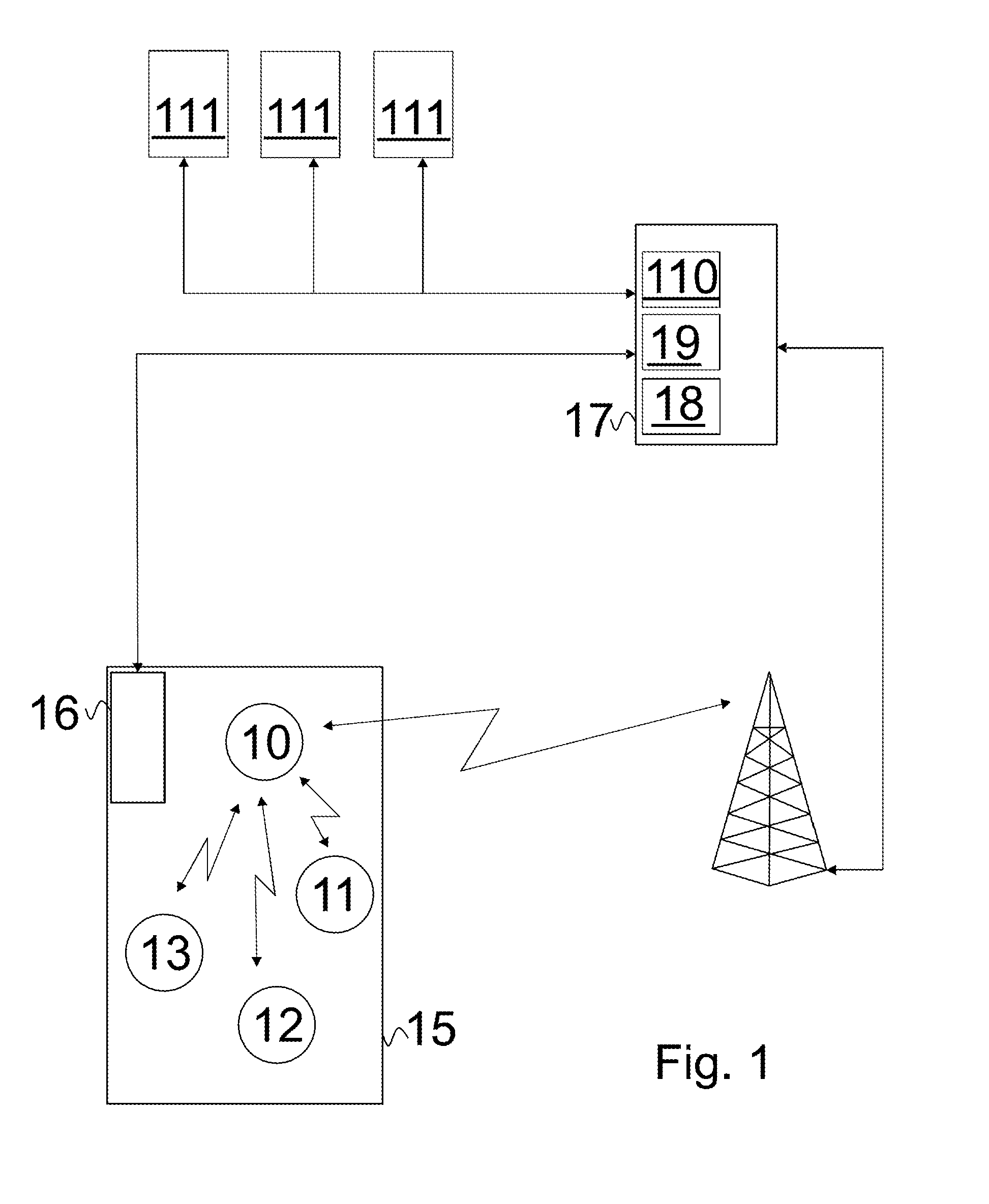
[0021]In FIG. 1 a block diagram of an example embodiment according to the present invention is disclosed. In FIG. 1 four persons 10-13 are located in an elevator car 14. It is assumed that each of the persons have a mobile device being capable of short distance communication. Typical example of such a short distance communication is a Bluetooth connection between devices, however, any other suitable communication method may be used. The elevator is controlled by a person 10 using an electronic key that allows the holder of the key to choose a destination floor according to the access rights. The key used may be a separate conventional electronic key or, for example a near field communication (NFC) functionality in a mobile device. The mobile device may be, for example, mobile phone, laptop computer or touch screen computer, such as Ap...


PUM


Abstract

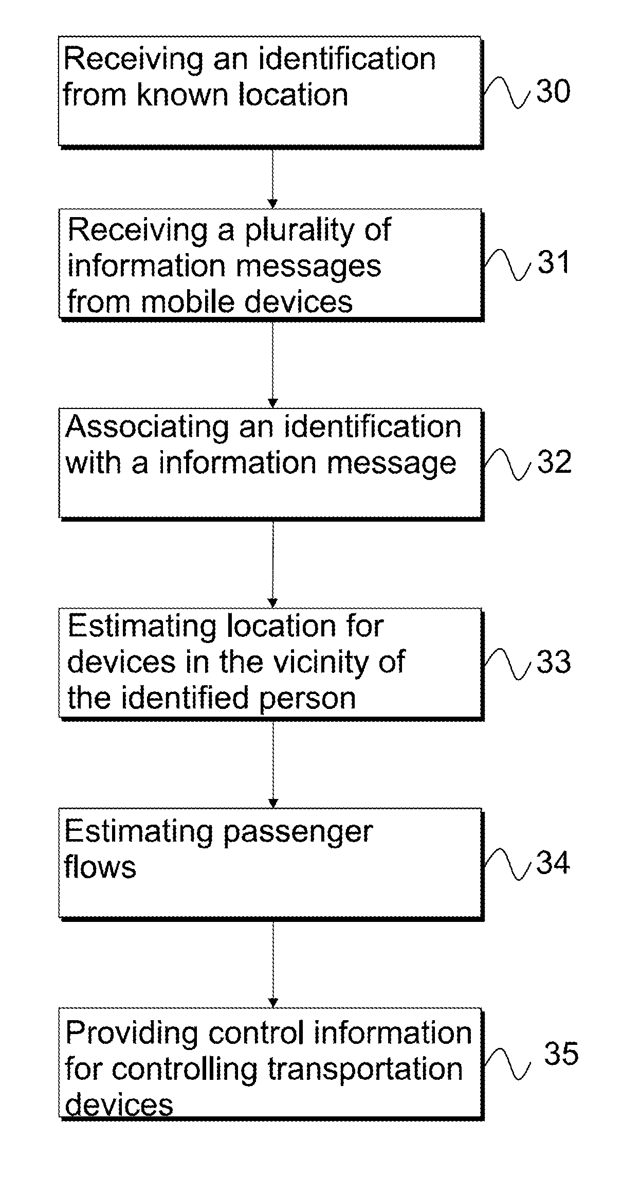
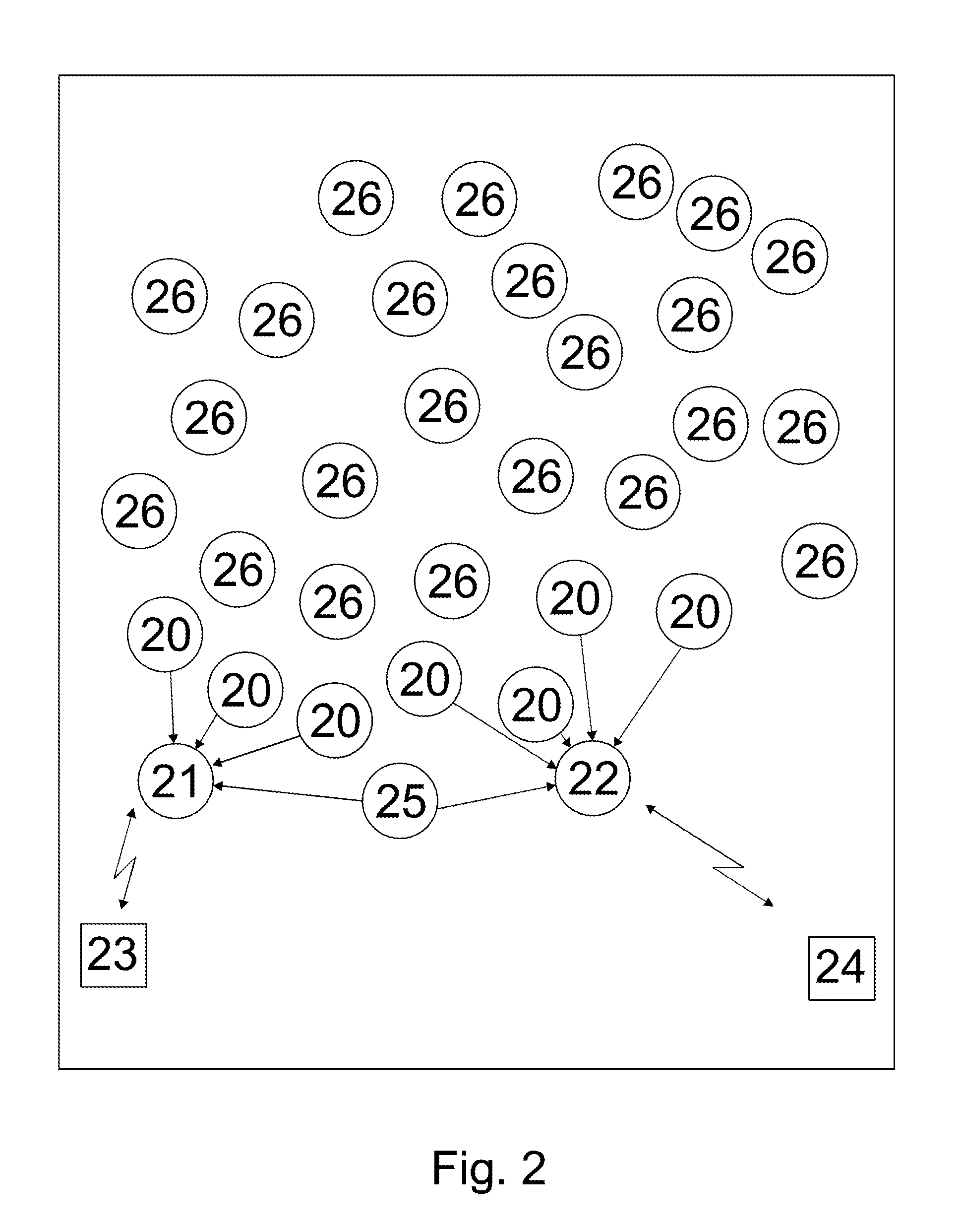
A mechanism for generating information about passenger flows. Mobile devices of passengers are used for providing information about other devices in the vicinity. The location of the device providing information detects other devices in the vicinity and transmits the information to a central system. Then, the central system associates this information with a location of a person when this person is identified by using an identification device attached to a gate, elevator or other transportation device. When the location of the person identified is known, the location persons having mobile devices in the vicinity can be estimated. Based on this continuously collected information passenger flows can be estimated and based on passenger flows control information for controlling transportation devices can be formed.

Description

[0001]This application is a continuation of PCT International Application No. PCT / FI2013 / 050475 which has an International filing date of Apr. 26, 2013, the entire contents of which are incorporated herein by reference.FIELD OF THE INVENTION[0002]The invention relates to passenger flow management and more particularly, to a mechanism for providing control information for transportation devices based on passenger flows.BACKGROUND OF THE INVENTION[0003]Public places have a plurality of transportation devices, such as elevators, escalators and similar. Depending on the application they may be programmed to take passenger flows into account. In the simple mechanism this is based, for example, to known high traffic hours. For example, there is a group of escalators comprising three separate escalators. When the direction of traffic is known, the group can be configured such that two escalators operate into the busier direction. Correspondingly, it is known that elevators may be brought t...

Claims


Application Information

Patent Timeline
Patent Type & Authority Applications(United States)
IPC IPC(8): B66B1/34G05B15/02H04W4/02H04W4/029
CPCB66B1/3476G05B15/02B66B1/3446H04W4/02H04B17/00H04W4/029
Inventor ELOMAA, NIKO
Owner KONE CORP
Learn More