Bearing member, end member, photoreceptor-drum unit, and process cartridge

a technology of photoreceptor and process cartridge, which is applied in the field of process cartridges, can solve the problems of deteriorating productivity, affecting the accuracy of assembly, and affecting the quality of assembly, so as to prevent the shaft member from falling out, easy to attach and detach the process cartridge, and easy to attach and detach the shaft member

Active Publication Date: 2016-01-21
MITSUBISHI CHEM CORP
View PDF5 Cites 15 Cited by
  • Summary
  • Abstract
  • Description
  • Claims
  • Application Information

AI Technical Summary

Benefits of technology

[0017]Here, in consideration of the above-described problems, a non-limited object of the present invention is to provide a bearing member, which can be easily produced by suppressing issues, such as damage, with high precision, while it is possible to prevent the shaft member from being unintentionally detached, to allow the shaft member to smoothly swing, to transmit a rotating force, and to attach and detach the shaft member to and from the apparatus body. In addition, there are provided an end member which is provided with the bearing member, a photoreceptor-drum unit, and a process cartridge.
[0030]According to the present invention, it may be easy to attach the shaft member to the bearing member, the shaft member swings smoothly after the attachment, and it is possible to prevent the shaft member from unintentionally falling out. In addition, it is possible to transmit a rotational driving force from the apparatus body to the photoreceptor drum, and it is also easy to attach and detach the process cartridge to and from the apparatus body.
[0032]According to this, when the shaft member is attached to the bearing member, since it is not necessary to strongly attach and detach the shaft member, accuracy of assembly of the shaft member and the bearing member does not deteriorate.

Problems solved by technology

In assembling the spherical section by forcibly pulling in and out, there is a concern that assembly precision deteriorates or components are damaged during assembly.
According to this, there are no issues, such as the forcible pulling in and out, but there are still the issues of man-hours increasing, and productivity deteriorating.
In addition, it is difficult to attach the drum flange (bearing member), in which the coupling member (shaft member) that swings in such a manner is attached, to an end section of the photoreceptor drum with high precision.
In addition, it takes a lot of effort and time to remove the shaft member from the bearing member when the shaft member is reused.
It is easy to attach the shaft member to and detach the shaft member from the bearing member in the technology described in Japan Institute of Invention and Innovation Journal of Technical disclosure, Japan Institute for Promoting Invention and Innovation No. 2010-502200, but there is a concern that the shaft member is detached from the bearing member without intention.
In addition, there is a case where it is difficult to realize smooth swinging of the shaft member and smooth attachment and detachment of the shaft member from the apparatus body.

Method used


Image

  • Bearing member, end member, photoreceptor-drum unit, and process cartridge
  • Bearing member, end member, photoreceptor-drum unit, and process cartridge
  • Bearing member, end member, photoreceptor-drum unit, and process cartridge

Examples


Embodiment Construction

[0068]The above-described effects and advantages of the present invention are apparent from the embodiments for implementing the invention which will be described in the following. Hereinafter, the present invention will be described based on the embodiments illustrated in the drawings. However, the present invention is not limited to the embodiments.

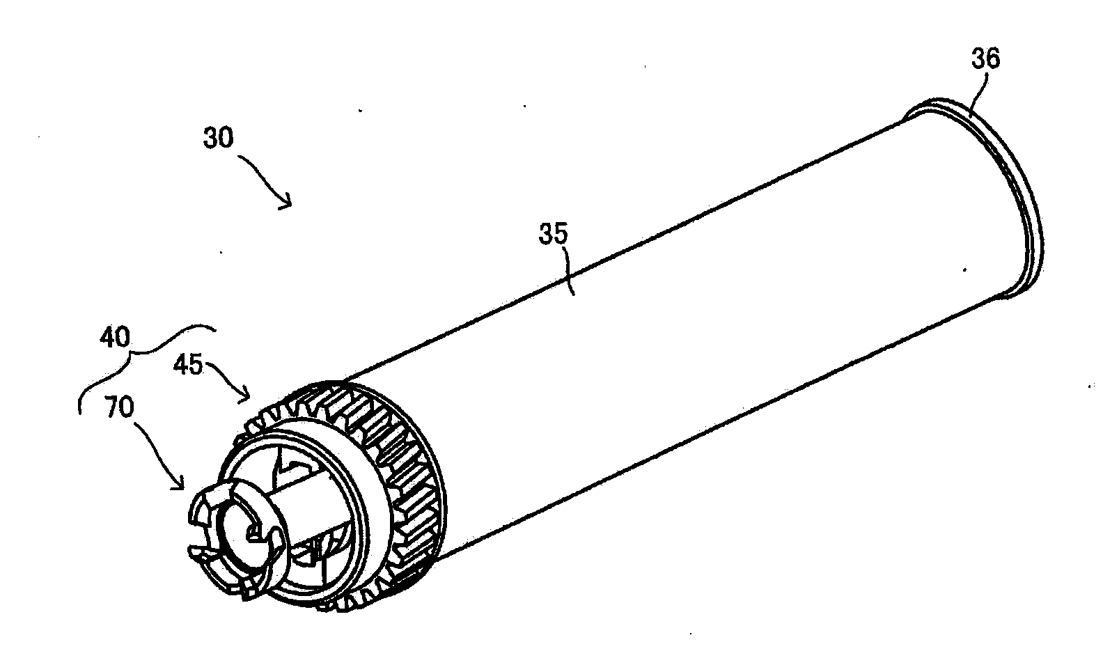
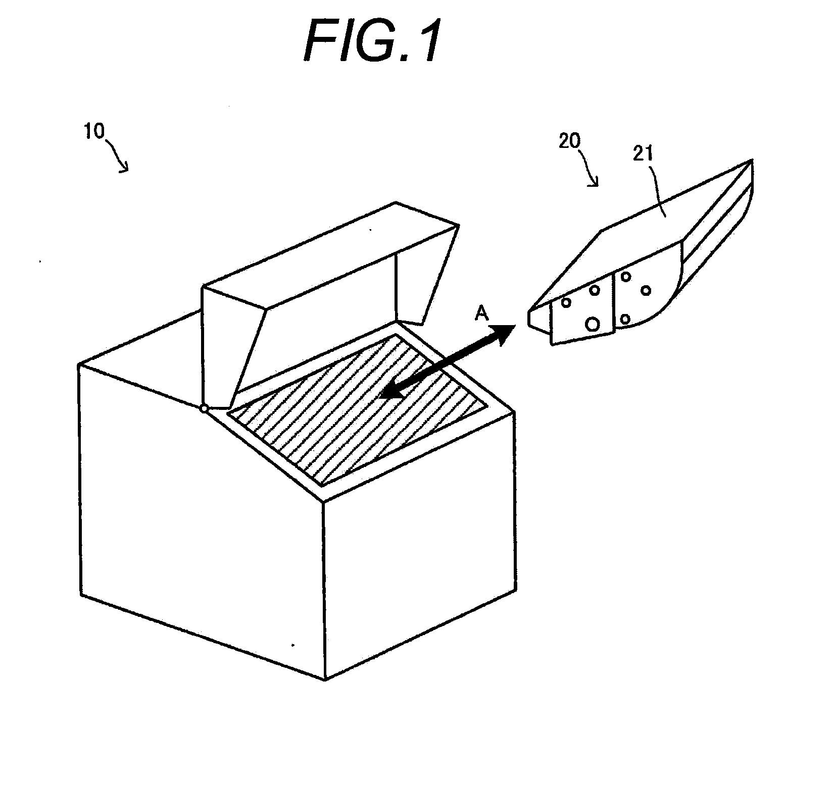
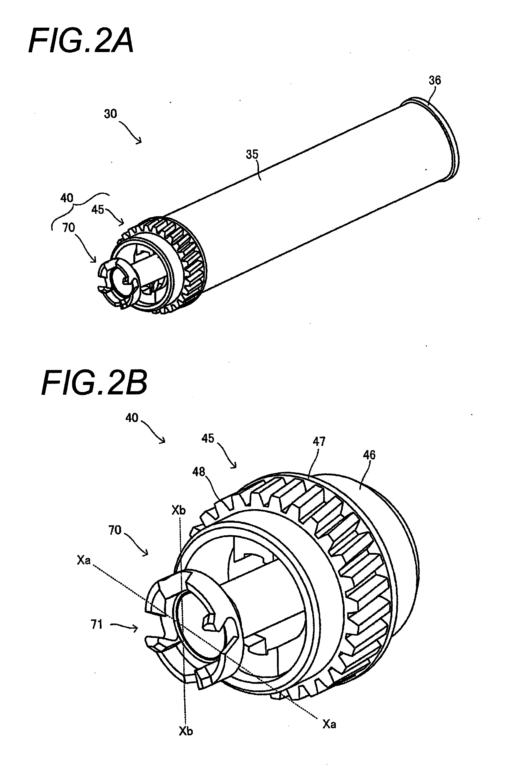
[0069]FIG. 1 is a diagram illustrating one embodiment, and is a perspective view schematically illustrating a process cartridge 20 which is provided with a bearing member 45 (refer to FIG. 2A), and an image forming apparatus body 10 (hereinafter, there is a case where the image forming apparatus body 10 is described as an “apparatus body 10”) which has the process cartridge 20 mounted thereon for use. The process cartridge 20 illustrated in FIG. 1 can be mounted onto and detached from the apparatus body 10 by being moved in a direction illustrated with A in FIG. 1. The direction is a direction which is different from an axial line direc...


PUM


Abstract

There is provided a bearing member which is disposed at an end section of a photoreceptor drum for attaching a shaft member that transmits a rotating force to the bearing member, the bearing member including a tubular body, and a holding section which is disposed inside the tubular body attachably and detachably, and holds a rotating force transmission pin provided in the shaft member, wherein the holding section includes at least two swing grooves provided extending along an axial direction of the tubular body, and opposing each other, and introduction grooves, each having one end communicating with the swing groove and the other end communicating with an outside of the swing groove, and the introduction grooves in a posture in which the shaft member transmits the rotating force are disposed entirely at a position to be lower than an entirety or a part of the rotating force transmission pin.

Description

CROSS REFERENCE TO RELATED APPLICATION(S)[0001]This application is a continuation of International Patent Application No. PCT / JP2014 / 058133 filed on Mar. 24, 2014, claiming the benefit of priority of Japanese Patent Application No. 2013-063794 filed on Mar. 26, 2013, the contents of which are incorporated herein by reference in its entirety.BACKGROUND OF THE INVENTION[0002]1. Field of the Invention[0003]The present invention relates to a process cartridge which is provided to be attachable to and detachable from an image forming apparatus, such as a laser printer or a copying machine, a photoreceptor-drum unit which is provided in the process cartridge, an end member which is mounted on a photoreceptor drum of the photoreceptor-drum unit, and a bearing member which configures the end member.[0004]2. Description of the Related Art[0005]In an image forming apparatus, such as a laser printer or a copying machine, a process cartridge which is attachable to and detachable from an image f...

Claims


Application Information

Patent Timeline
Patent Type & Authority Applications(United States)
IPC IPC(8): G03G15/00
CPCG03G15/757G03G21/1647G03G21/186G03G15/751
Inventor IIJIMA, SHINICHIIKEDA, SHUICHI
Owner MITSUBISHI CHEM CORP
Why Eureka
Try Eureka