Video surveillence system for detecting firearms

a video surveillance and firearm technology, applied in the field of surveillance systems, can solve problems such as unacceptable cost increase, certain issues in video surveillance, and short attention span

Inactive Publication Date: 2016-01-21
MARTIN MICHAEL SCOTT +1
View PDF10 Cites 36 Cited by
  • Summary
  • Abstract
  • Description
  • Claims
  • Application Information

AI Technical Summary

Benefits of technology

[0018]The present invention further teaches that the trained classifier of the system of the system may be taught by special methods adapted to the firearm recognition area, in particular, exposure of the trained classifier to pre-categorized images so that it learns firearm recognition very effectively.

Problems solved by technology

However, video surveillance has certain issues, most notably the fact that it must of needs be monitored by a human operator.
Since monitoring a video camera scene is fairly uninteresting work under most circumstances, operators tend to allow their attention to wander and even with utmost effort, the human attention span is known to be about 15 minutes, even less if the individual is uninterested.
In some environments such as pool life guarding it is practical to rotate the guards every 12 minutes or so, but in the case of multiple video surveillance monitors this solution will drive up costs unacceptably.
The computer does not allow its attention to wander.
However, recognition of faces only carries surveillance technology forward to a certain degree.

Method used


Image

  • Video surveillence system for detecting firearms
  • Video surveillence system for detecting firearms
  • Video surveillence system for detecting firearms

Examples


example one

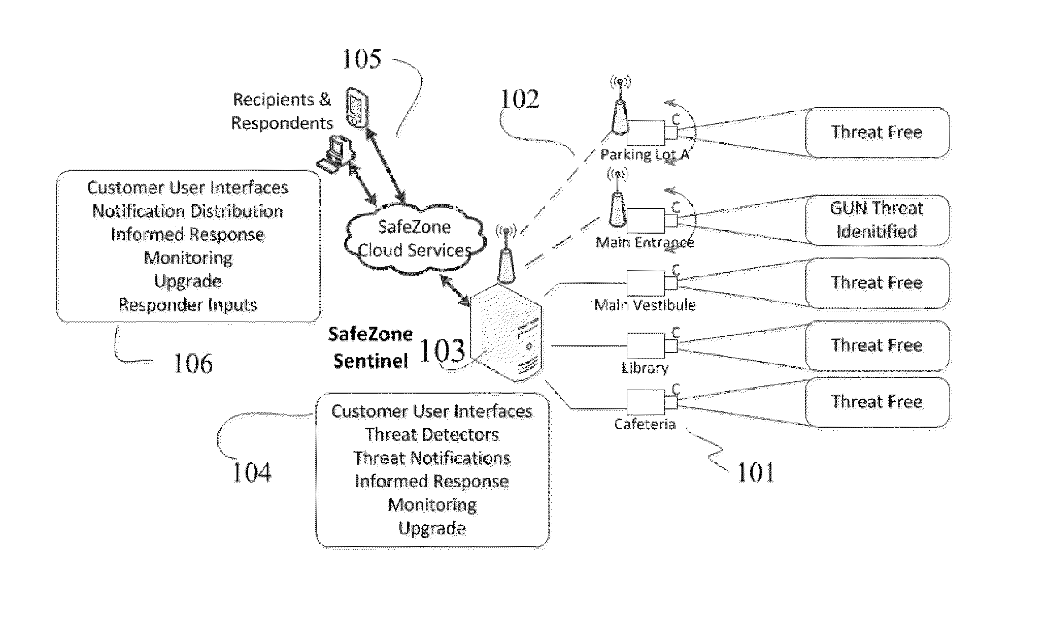
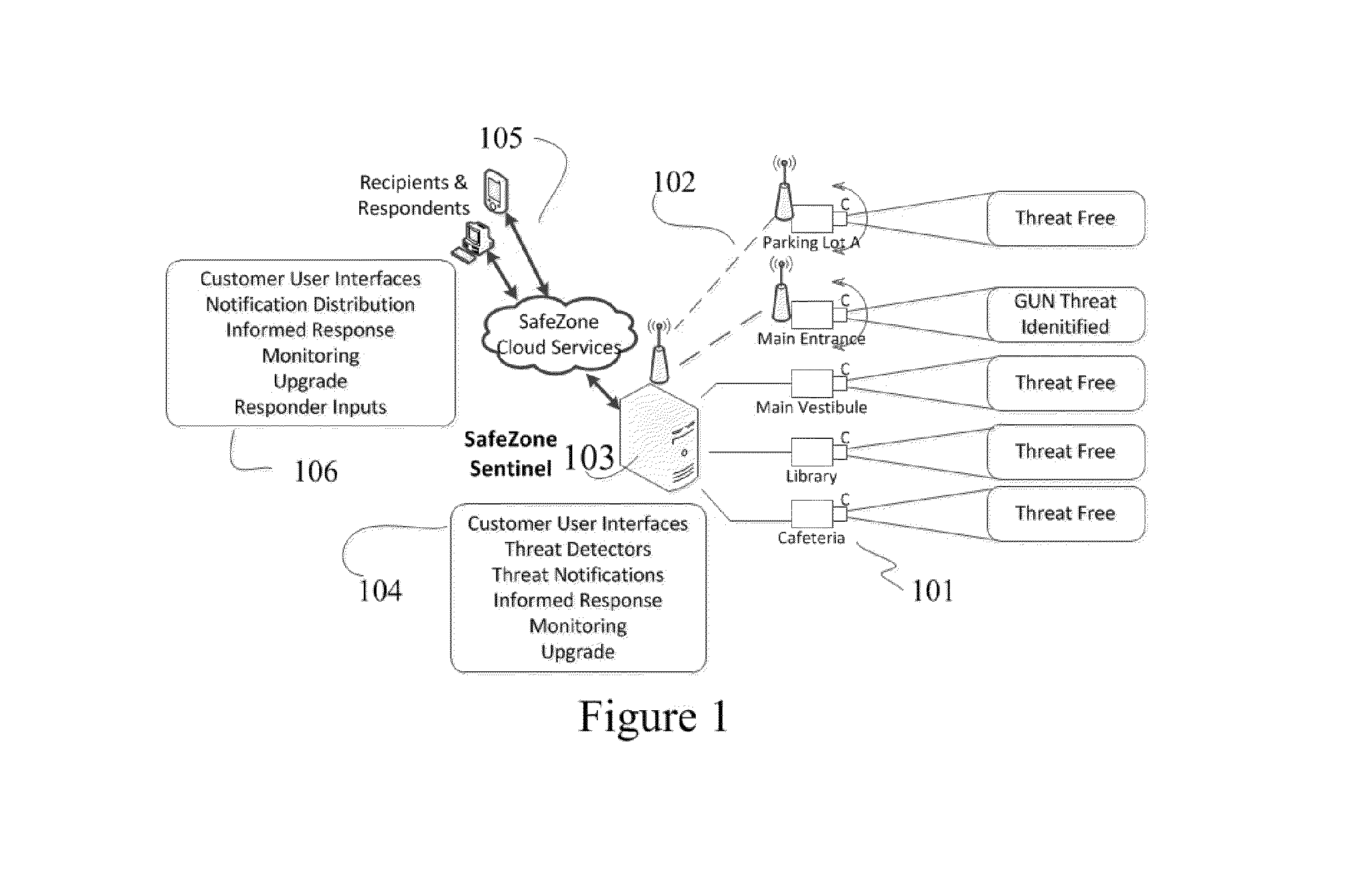
[0266]Following filing of the provisional application referenced above, a real-world technical test has been initiated by approaching a testing law enforcement organization and requesting their cooperation, after which a test system according to the present invention has been installed. The location is in a town having large quantities of foot traffic therethrough, carrying sporting equipment. The test facility is a multi-level parking structure including at its southwest corner a small three-level shopping and restaurant arcade with a number of commercial establishments therein. The initial configuration included 10 surveillance cameras tied in to the classification and alert system but is growing to include more. The testing organization reports that they desire to move from a system testing configuration (in particular, testing of the cascading classifiers) to a full coverage configuration. They report that after tuning the system does not return an excessive number of false posi...

example two

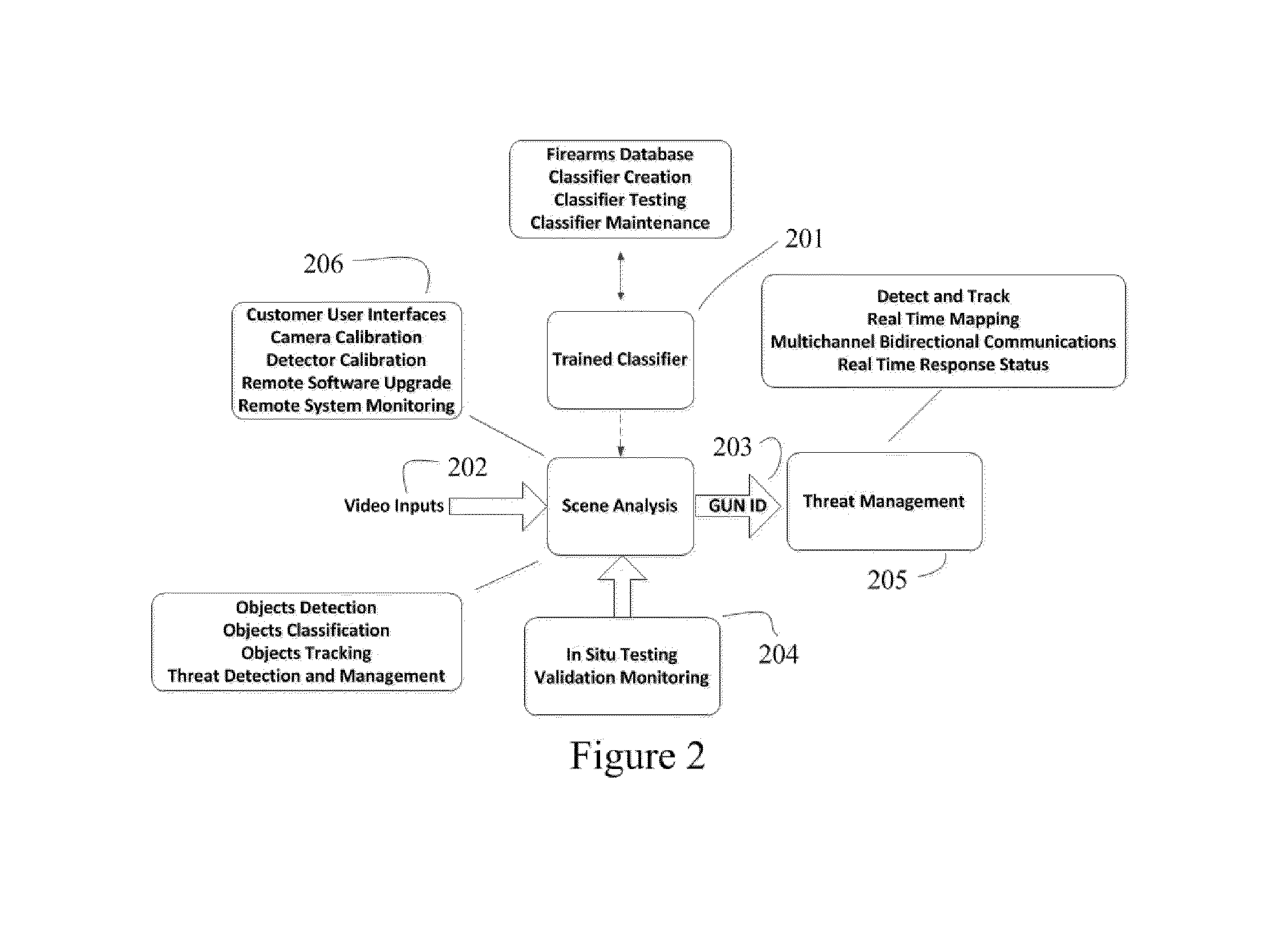
[0267]A classifier training system and facility is established in the metropolitan Denver area, this training system is partially visible in the following black and white diagrams. “Trained” cascading classifiers obviously require training before they can function, and happily real-world footage of gunmen walking through public places is fairly difficult to acquire. The secure and confidential training facility thus provides a confidential location at which images of gunmen can be produced and provided to the system of the invention so that the trained classifiers may be exposed to positive hits and refine their recognition algorithms.

[0268]In use, the exemplary gunmen pass through the fields of view of the network of cameras installed in the system, thus creating test video streams for the system. The video imagery is then fed through a classifier training module which uses the imagery to derive and / or refine the vectors / algorithms within the various stages of the cascading classif...


PUM


Abstract

The present invention teaches that a computer system can be taught to analyze a stream of video surveillance imagery for individuals carrying firearms using a machine vision and machine learning system of the cascading classifier type, taught by special methods adapted to the firearm recognition area, in particular, exposure of the trained classifier to pre-categorized firearm images, and may poll a number of types of recognition methods before making a positive firearm recognition.

Description

CROSS-REFERENCE TO RELATED APPLICATIONS[0001]This application claims the priority and benefit of co-pending U.S. Provisional Application No. 61 / 776,773 filed Mar. 11, 2013 in the name of the same inventors. The entirety of that application is incorporated herein by this reference.COPYRIGHT NOTICE[0002]A portion of the disclosure of this patent document contains material which is subject to copyright protection. The copyright owner has no objection to the facsimile reproduction by anyone of the patent document or the patent disclosure, as it appears in the Patent and Trademark Office patent file or records, but otherwise reserves all copyright rights whatsoever. 37 CFR 1.71(d).FIELD OF THE INVENTION[0003]This invention relates generally to surveillance systems, and specifically to video surveillance systems utilizing video imagery and computer analysis.STATEMENT REGARDING FEDERALLY FUNDED RESEARCH[0004]This invention was not made under contract with an agency of the US Government, no...

Claims


Application Information

Patent Timeline
Patent Type & Authority Applications(United States)
IPC IPC(8): G06K9/00G06K9/62G06T7/00H04N7/18
CPCG06K9/00771G06T7/0042G06T2207/20081H04N7/181G06K2209/09G06K9/6269G06V40/10G06V20/53G06V20/52
Inventor MARTIN, MICHAEL SCOTTSOLLER, JEREMY RYAN
Owner MARTIN MICHAEL SCOTT
Why Eureka
Try Eureka