Battery Cell for a Battery, Especially for a Traction Battery

a battery and battery technology, applied in the direction of batteries, cell components, current conducting connections, etc., can solve the problems of undesirable leakage, non-uniform contact between the sealing sleeve and the associated terminal, and inconvenient manufacturing process, so as to avoid stress whitening, reduce the risk of contact tabs and/or cell connectors possibly breaking off, and reduce the risk of corrosion

Active Publication Date: 2016-01-21
HOPPECKE BATTERIEN
View PDF1 Cites 5 Cited by
  • Summary
  • Abstract
  • Description
  • Claims
  • Application Information

AI Technical Summary

Benefits of technology

[0024]According to a further feature of the invention, the cap comprises two parts, i.e., a first part which is fused or welded to the casing cover as well as a second part which is axially spaced from the first part, wherein between the first part and the second part an elastically configured connecting bridge is formed. According to this construction, the second part of the cap is capable of performing a relative movement relative to the first part of the cap, i.e., relative to the part of the cap that is fused or welded to the casing cover, in axial direction, i.e., in vertical direction of the cap or height direction of the cap. This relative mobility of the second part of the cap enables in an advantageous way a length compensation which aids in preventing so-called stress whitening on the casing cover.
[0025]Over the service life of a battery, intercrystalline corrosion may lead to growth of the positive plates in vertical (height) direction. As a result of this, the terminals of the positive plates will push from below against the casing cover. This can cause so-called stress whitening. Stress whitening refers to microscopically small areas whose boundary surfaces are bridged with individual extremely stretched material strands and which become visible as milky-white discolorations. Stress whitening is thus an initial damage of the material and may be the beginning of complete material failure. In order to counteract this, the invention proposes the two-part configuration of the cap, where the two parts of the cap are coupled with each other by an elastically formed connecting bridge. This elastic connecting bridge enables in operation a height compensation in vertical direction so that the terminals of the positive plates can migrate and stress whitening is avoided.
[0026]According to a further feature of the invention, it is provided that the cap is arranged with an anti-rotation connection on the terminal. This protects the terminal from a possible cell connector break, in particular in case of a configuration with a corresponding screw connection for contacting a connecting cable.
[0027]Typically, for contacting a connecting cable on the respective terminal, it is provided that the connecting cable is to be screw-connected to the terminal. This screw-on action is realized with application of a torque of, for example, 20 Nm. The abutment for the screw is formed by the terminal or a threaded sleeve received in the terminal and comprised of nonferrous metal. The terminal is supported, in turn, on the cell connector and thus on the corresponding electrode plates, wherein the connection of the electrode plates with the cell connector is realized only by the respective contact tabs which constitute a particular weak link. In case of proper attachment of a connecting cable by means of the corresponding screw on the terminal, particularly in case of comparatively narrow batteries, i.e., those that comprise only a few electrode plates, it may happen that the contact tabs of the individual electrode plates that are connected to the cell connector bend or even tear off at the moment of torque application. In order to counteract this problem, the invention proposes to arrange the cap with anti-rotation fixation on the terminal. This anti-rotation arrangement ensures that, when screwing in a connecting screw for connecting a connecting cable, the introduced torque is introduced by means of the anti-rotation contact of cap and terminal into the cap and from there via the weld connection into the casing cover. In this way, the risk of contact tabs and / or cell connectors possibly breaking off is eliminated.
[0028]The anti-rotation connection of the cap and the terminal can be realized, for example, in that the cap has a slot which is extending in the vertical direction or height direction of the cap and which is engaged by a sword-like projection of the terminal. In this way, a form-fit connection between the cap, on the one hand, and the terminal, on the other hand, is formed. This connection is capable of transmitting torque so that dissipation into the casing cover or the casing box which is fused thereto can be realized. In this connection, the configuration of the sword-like projection on the terminal has moreover the advantage that the terminal can also be produced in the context of the afore described COS method.
[0029]The invention as a whole proposes a construction which, compared to the prior art, enables a significantly improved terminal sealing action in conjunction with simultaneous use of the COS method for terminal manufacture so that the use of an inexpensive manufacturing process that is easy to carry out is provided.

Problems solved by technology

Even though the afore described construction has proven successful in day-to-day practical use, it has its disadvantages; in particular, the sealing action between sealing sleeve, on the one hand, and the associated terminal, on the other hand, is not satisfactory over the course of time.
Moreover, the terminals also can be oriented such that they are displaced relative to each other like skew lines; this may also lead to non-uniform contacting of the respective sealing sleeve on the associated terminal.
This also may cause undesirable leakages already after only a very short period of use of the battery cell.
In this context, there is a particular problem in that sulfuric acid is characterized by a relatively great capillary action so that the electrolyte over time will pass even through smallest cracks and gaps.
Possible imprecision in regard to the contacting action of the sealing sleeve on the associated terminal therefore compounds the problem of leakage.

Method used


Image

  • Battery Cell for a Battery, Especially for a Traction Battery
  • Battery Cell for a Battery, Especially for a Traction Battery
  • Battery Cell for a Battery, Especially for a Traction Battery

Examples


Embodiment Construction

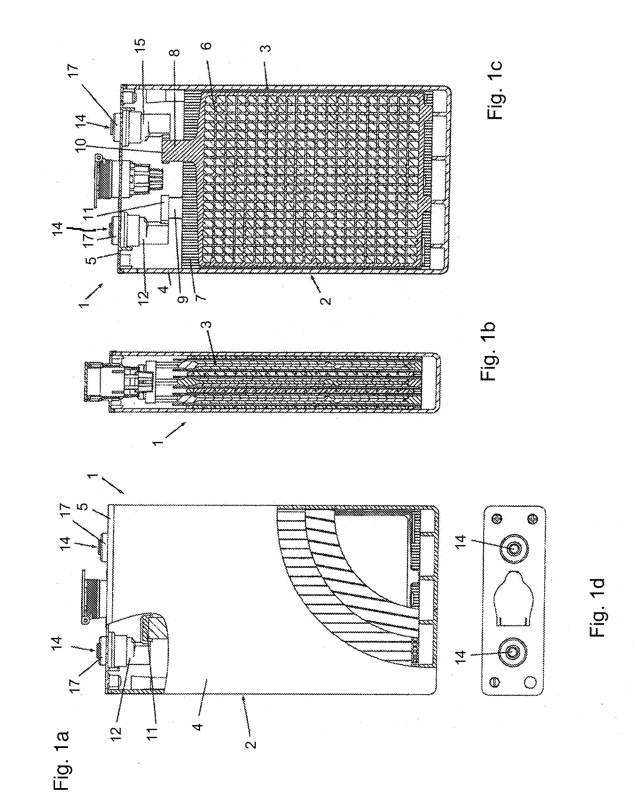
[0043]FIGS. 1a to 1d show in schematic illustrations a battery cell 1 according to the invention.

[0044]The battery cell 1 comprises a casing 2. The casing 2 comprises a casing box 4 and a casing cover 5 that in the final mounted state fluid-tightly closes off the casing box 4. The casing box 4 and the casing cover 5 are preferably connected by welding or fusing to each other.

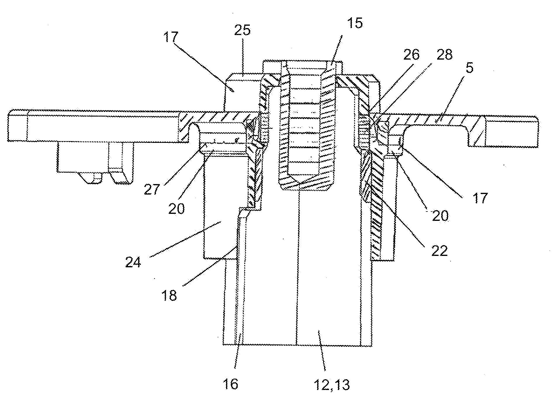
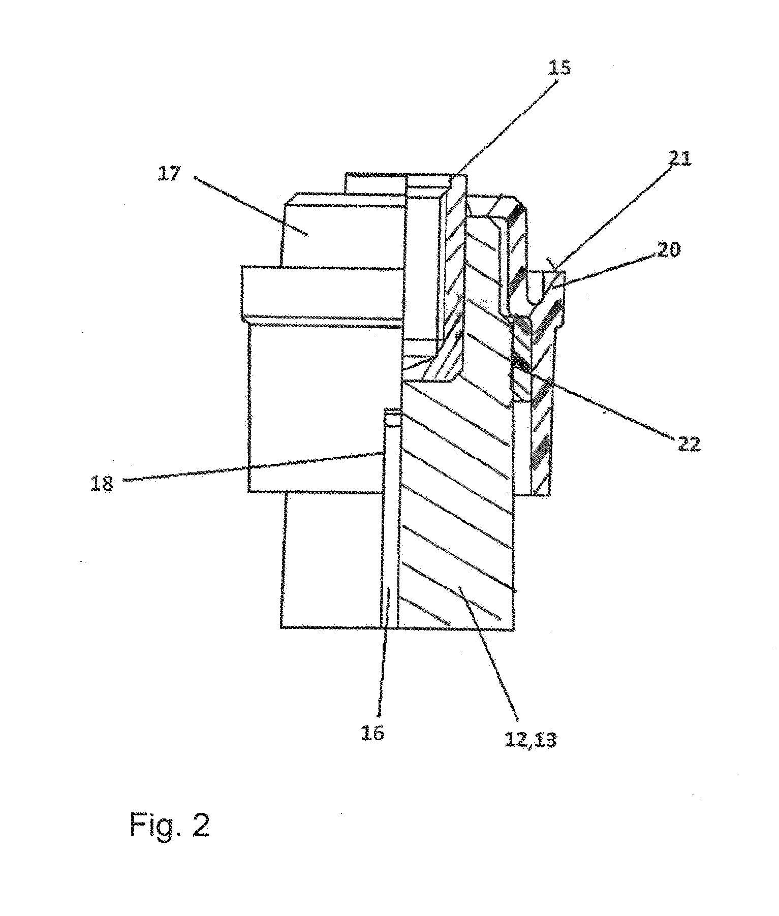
[0045]Within the casing 2, an electrode plate pack 3 is arranged. The pack 3 is comprised of alternatingly arranged positive electrode plates 6 and negative electrode plates 7. The electrode plates 6 and 7 comprise contact tabs at the side facing the casing cover 5, wherein the positive electrode plates 6 are provided with contact tabs 8 and the negative electrode plates 7 are provided with contact tabs 9. By means of a common cell connector 10 or 11, respectively, the contact tabs 8 or contact tabs 9 are electrically coupled to each other. Each cell connector 10 or 11 supports a terminal 12 or 13, wherein the c...


PUM

PropertyMeasurementUnit
output voltageaaaaaaaaaa

Abstract

A battery cell has an electrode plate pack arranged in a casing and provided with a terminal of lead material that extends through a cover opening of the casing cover of the casing. A plastic material cap is placed onto the terminal. The cap has an inner side provided with a circumferentially extending shoulder and an exterior side provided with a circumferentially extending support web. A sealing element is arranged at the inner side of the cap between cap and terminal and is positionally fixed by the circumferentially extending shoulder. The casing cover rests on the circumferentially extending support web. Cap and casing cover are welded to each other. A threaded sleeve of nonferrous metal is embedded in the lead material of the terminal and is aligned with an insertion opening of the cap. The threaded sleeve receives a connecting screw to be passed through the insertion opening.

Description

BACKGROUND OF THE INVENTION[0001]The invention relates to a battery cell for a battery, especially for a traction battery, comprising a casing box that is open at one side and a casing cover that closes off the open side of the casing box in a fluid-tight way as well as comprising an electrode plate pack arranged within the casing box that is provided with a terminal that is passed through an opening provided within the casing cover.[0002]Battery cells of the aforementioned kind, on the one hand, and traction batteries that comprise a plurality of battery cells electrically connected to each other, on the other hand, are well known in the prior art so that supporting documentation by printed publications is not required in this context.[0003]As non-stationary batteries, traction batteries are typically employed in automotive technology, for example, in forklifts, elevating trucks and the like. Known traction batteries comprise a plurality of battery cells that are electrically conne...

Claims


Application Information

Patent Timeline
Patent Type & Authority Applications(United States)
IPC IPC(8): H01M50/103H01M50/147H01M50/176H01M50/186H01M50/193H01M50/50H01M50/55H01M50/553H01M50/567
CPCH01M2/06H01M2220/20H01M2/024H01M50/147H01M50/50H01M50/553H01M50/193H01M50/186H01M50/55H01M50/176H01M50/103H01M50/567Y02E60/10H01M50/15
Inventor KESPER, HEINRICH
Owner HOPPECKE BATTERIEN
Why Eureka
Try Eureka