Robot system control method and robot system

a robot system and robot technology, applied in the direction of electric programme control, program control, instruments, etc., can solve the problems of reducing operating efficiency and difficulty in tcp matching between working robots, and achieve the effect of increasing the operating efficiency of the operator

Active Publication Date: 2016-01-28
PANASONIC INTELLECTUAL PROPERTY MANAGEMENT CO LTD
View PDF9 Cites 43 Cited by
  • Summary
  • Abstract
  • Description
  • Claims
  • Application Information

AI Technical Summary

Benefits of technology

[0012]As described above, in accordance with the present disclosure, in the state where a working robot that can perform TCP matching with only part of th

Problems solved by technology

However, depending on the positions of the plurality of robots that form a robot system, the

Method used


Image

  • Robot system control method and robot system
  • Robot system control method and robot system
  • Robot system control method and robot system

Examples


first exemplary embodiment

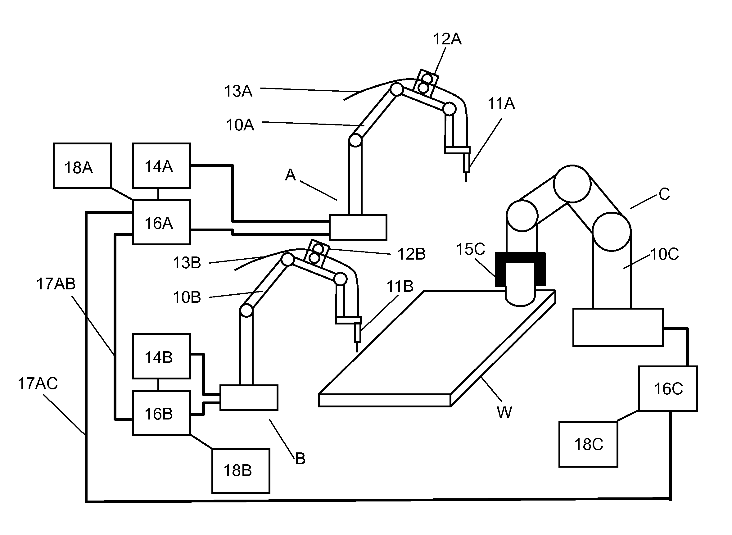
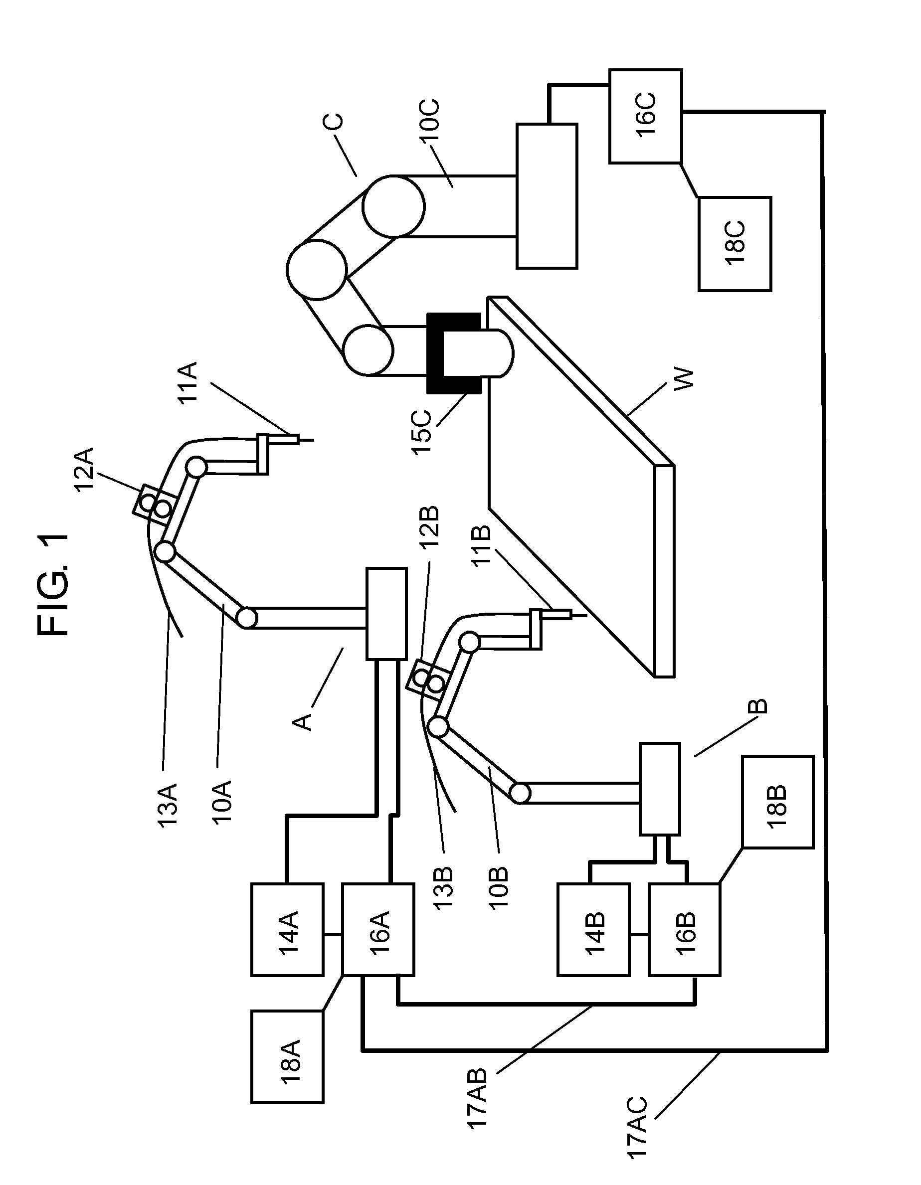
[0023]FIG. 1 is a diagram showing a robot system in which three robots cooperatively perform a welding operation in accordance with this exemplary embodiment. In this robot system, robot A (a master robot) and robot B (a second slave robot) are working robots for welding operation, and robot C (a first slave robot) is a handling robot for holding a work piece.

[0024]Robot A includes manipulator 10A, welding torch 11A, welding wire feeder 12A, welding wire 13A, welding machine 14A, and controller 16A.

[0025]Welding machine 14A is electrically connected to welding torch 11A and controls welding current and welding voltage. Welding machine 14A is electrically connected to welding wire feeder 12A, and controls the feeding speed of welding wire 13A.

[0026]Robot B includes manipulator 10B, welding torch 11B, welding wire feeder 12B, welding wire 13B, welding machine 14B, and controller 16B. Welding machine 14B is electrically connected to welding torch 11B and controls welding current and we...


PUM


Abstract

A robot system control method includes a first step through a fifth step. Particularly in the second step, a second transformation matrix that represents the positional relation between a first slave robot and a second slave robot is generated and stored in a master robot. In the fourth step, based on a second command obtained using a first transformation matrix and the second transformation matrix, the master robot instructs the second slave robot to operate. In the fifth step, the first slave robot and the second slave robot perform a cooperative operation with the master robot. Thus, in the state where a working robot that can perform TCP matching with only part of the other robots is set to a master robot, all of the robots can perform a cooperative operation.

Description

TECHNICAL FIELD[0001]The present disclosure relates to a method for controlling a robot system and to a robot system, using industrial robots, particularly to a robot system in which a plurality of robots operates in cooperation with each other.BACKGROUND ART[0002]Recently, a robot system has been required to perform an operation on a wide variety of complicated work pieces. Particularly, a robot system needs to be used in diversified small-quantity production. Further, in a robot system, the number of facilities including robots, and the installation area need to be suppressed. For this purpose, the following robot system is introduced. In this robot system, a jig peculiar to each work piece is not used, and a robot for holding a working tool and a robot for holding a work piece are operated in cooperation with each other (hereinafter referred to as a cooperative operation).[0003]FIG. 9 is a diagram showing an example of a conventional robot system using two robots. In FIG. 9, robo...

Claims


Application Information

Patent Timeline
IPC IPC(8): B25J9/16B25J3/00B25J9/00
CPCB25J9/1682B25J9/1607Y10S901/08B25J9/0084B25J3/00G05B2219/39121G05B2219/39132G05B2219/39139
Inventor KOMATSU, TAKAMICHIIKEDA, TATSUYA
Owner PANASONIC INTELLECTUAL PROPERTY MANAGEMENT CO LTD
Why Eureka
Try Eureka