
Pneumatic tire

a technology of pneumatic tires and tyres, which is applied in the direction of tyre tread bands/patterns, non-skid devices, vehicle components, etc., can solve the problems of deterioration of irregular wear resistance and other problems, and achieve the improvement of high-speed durability and linear handling. , the effect of increasing the arrangement density

Inactive Publication Date: 2016-01-28
TOYO TIRE & RUBBER CO LTD
View PDF0 Cites 9 Cited by
  • Summary
  • Abstract
  • Description
  • Claims
  • Application Information

AI Technical Summary

Benefits of technology

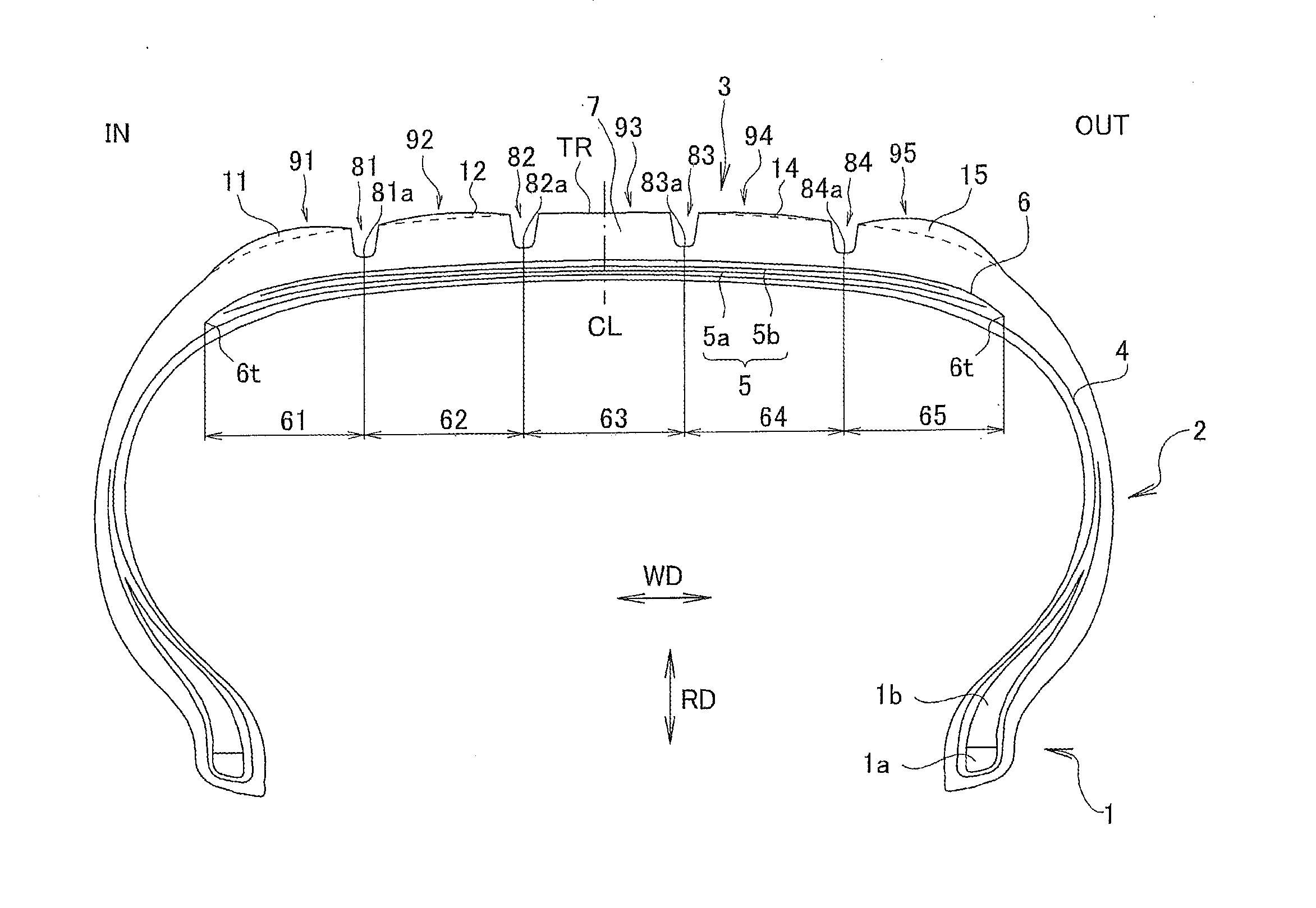
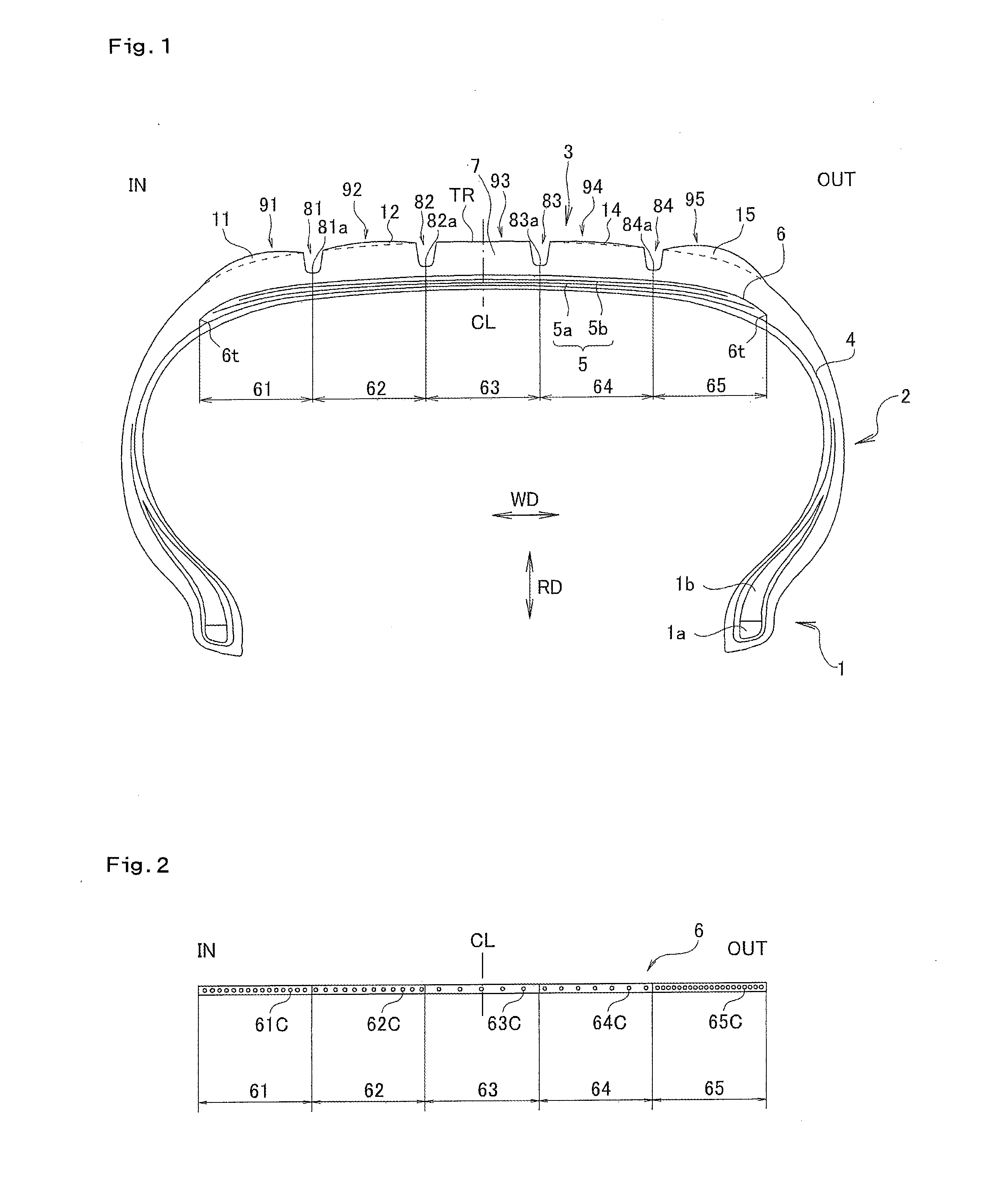
The present invention is about a pneumatic tire that can provide enough cornering power when the vehicle turns while maintaining a proper conicity. The tire has a belt reinforcing layer with a higher arrangement density of reinforcing cords in the outer area of the tire. This helps to optimize the reinforcement strength at the right and left shoulder portions of the tire equator, allowing for a sufficient cornering power while suppressing an increase in weight. The arrangement density of reinforcing cords in the inner area of the tire is also higher to further improve its strength. Additionally, a protruding portion may not be provided in the ground surface of the land portion to improve high-speed durability and linearity of handling.

Problems solved by technology

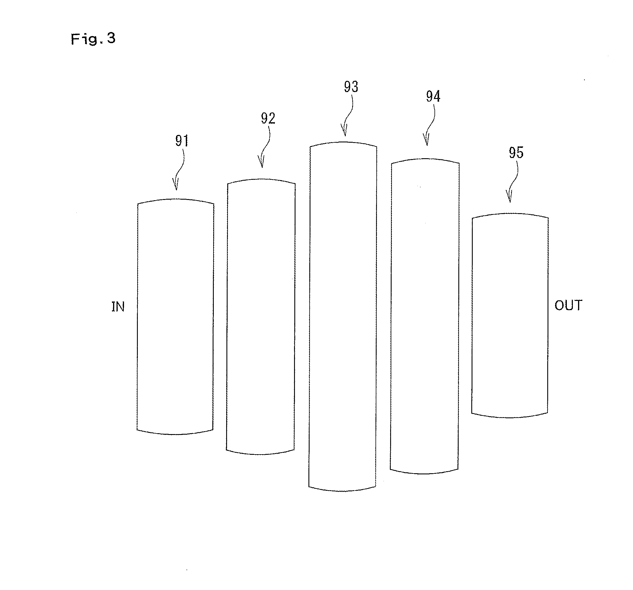
Since a ground contact length becomes shorter by making the arrangement density of the reinforcing cord higher, a ground contact shape becomes irregular in the case that the arrangement density of the reinforcing cord is differentiated in each of the areas, so that the ground contact shape becomes irregular, and there is a risk that an irregular wear resistance is deteriorated.

Method used


Image

  • Pneumatic tire
  • Pneumatic tire
  • Pneumatic tire

Examples


examples

[0054]The description will be given below of examples which specifically show the structure and the effect of the present invention. Evaluation items in the examples will be measured as follows.

[0055]Irregular Wear Resistance

[0056]A tire was installed to an actual car, a tire wear amount was measured after traveling at 15000 km on a dry road, the wear amount was measured at a center portion and a shoulder portion on a tread surface, and an irregular wear ratio (the wear amount of the shoulder portion / the wear amount of the center portion) was calculated. As the irregular wear ratio is closer to 1.0, the wear is more even, thereby indicating an excellent irregular wear resistance.

[0057]The pneumatic tire shown in FIG. 1 was set to an example (referred to the ground contact shape in FIG. 4). The arrangement density d1 in the first area 61 was set to 30 per inch, the arrangement density d2 in the second area 62 was set to 25 per inch, the arrangement density d3 in the third area 63 was...


PUM

PropertyMeasurementUnit
Diameteraaaaaaaaaa
Densityaaaaaaaaaa
Heightaaaaaaaaaa

Abstract

A pneumatic tire includes a belt layer, a belt reinforcing layer in which a plurality of reinforcing cords are arranged, four main grooves, and land portions comparted by the four main grooves, wherein in the case that the belt reinforcing layer is partitioned into five areas in a tire width direction by the four main grooves, an arrangement density of the reinforcing cord in the fifth area is higher than that of the reinforcing cord in the first area, and an arrangement density of the reinforcing cord in the second area is higher than that of the reinforcing cord in the fourth area, and wherein protruding portions having protruding heights in proportion to the arrangement densities are provided on ground surfaces of the land portions which are positioned outside in the tire diametrical direction in the areas having the higher density than that of the third area.

Description

BACKGROUND OF THE INVENTION[0001]1. Field of the Invention[0002]The present invention relates to a pneumatic tire having a belt layer which is buried in a tread portion, and a belt reinforcing layer which is arranged in an outer side in a tire diametrical direction of the belt layer.[0003]2. Description of the Related Art[0004]Conventionally, in a pneumatic tire, for the purpose of improving a high-speed durability and improving a steering stability, one or more belt reinforcing layers are provided between the tread rubber and the belt layer.[0005]In the following patent document 1, there is described a pneumatic tire in which belt reinforcing layers constructed by an organic fiber are provided in an outer side of a belt layer, and a driving number of the belt reinforcing layers is reduced little by little from a bent end toward a center side, for the purpose of improving the high-speed durability without deteriorating a smooth handling property at the cornering.[0006]A tire ground ...

Claims


Application Information

Patent Timeline
IPC IPC(8): B60C9/20B60C11/04
CPCB60C9/20B60C11/04B60C2009/2029B60C2009/1828B60C2009/0071B60C9/2009B60C11/1376B60C2009/2271
Inventor SHIMA, SATOSHI
Owner TOYO TIRE & RUBBER CO LTD
Learn More