Tape spring deployable structure

a technology of deployable structure and tape spring, which is applied in the direction of transportation and packaging, aircrafts, and space-occupied rigid structures, etc., can solve the problems of high inertia and mass per unit area, large space occupation of rigid structures when in a stored position, and uncontrollable deployment of monostable tapes, etc., to optimize the volume of the deployable structure and reduce the space occupied. , the effect of simple production

Active Publication Date: 2016-01-28
THALES SA
View PDF4 Cites 15 Cited by
  • Summary
  • Abstract
  • Description
  • Claims
  • Application Information

AI Technical Summary

Benefits of technology

[0008]The invention seeks to alleviate all or some of the problems mentioned hereinabove by proposing a deployable structure for a flexible roll-up and deployable structure, having the advantage of occupying very little space, being...

Problems solved by technology

These structures have the advantage of having dynamic behaviour that is fully controlled but have the disadvantage of having a high inertia and a mass per unit area.
Furthermore, rigid structures when in a stored position occupy a significant amount of space under the cap of a launcher.
The deployment of monostable tapes is often disorganized and uncontrolled.
However, in both instances, when deployment is initiated it may be violent and generate shocks, which means to say that the entire tape spring may have a tendency to straighten out simultan...

Method used


Image

  • Tape spring deployable structure
  • Tape spring deployable structure
  • Tape spring deployable structure

Examples


Embodiment Construction

[0037]For the sake of clarity, the same elements will bear the same references in the various figures.

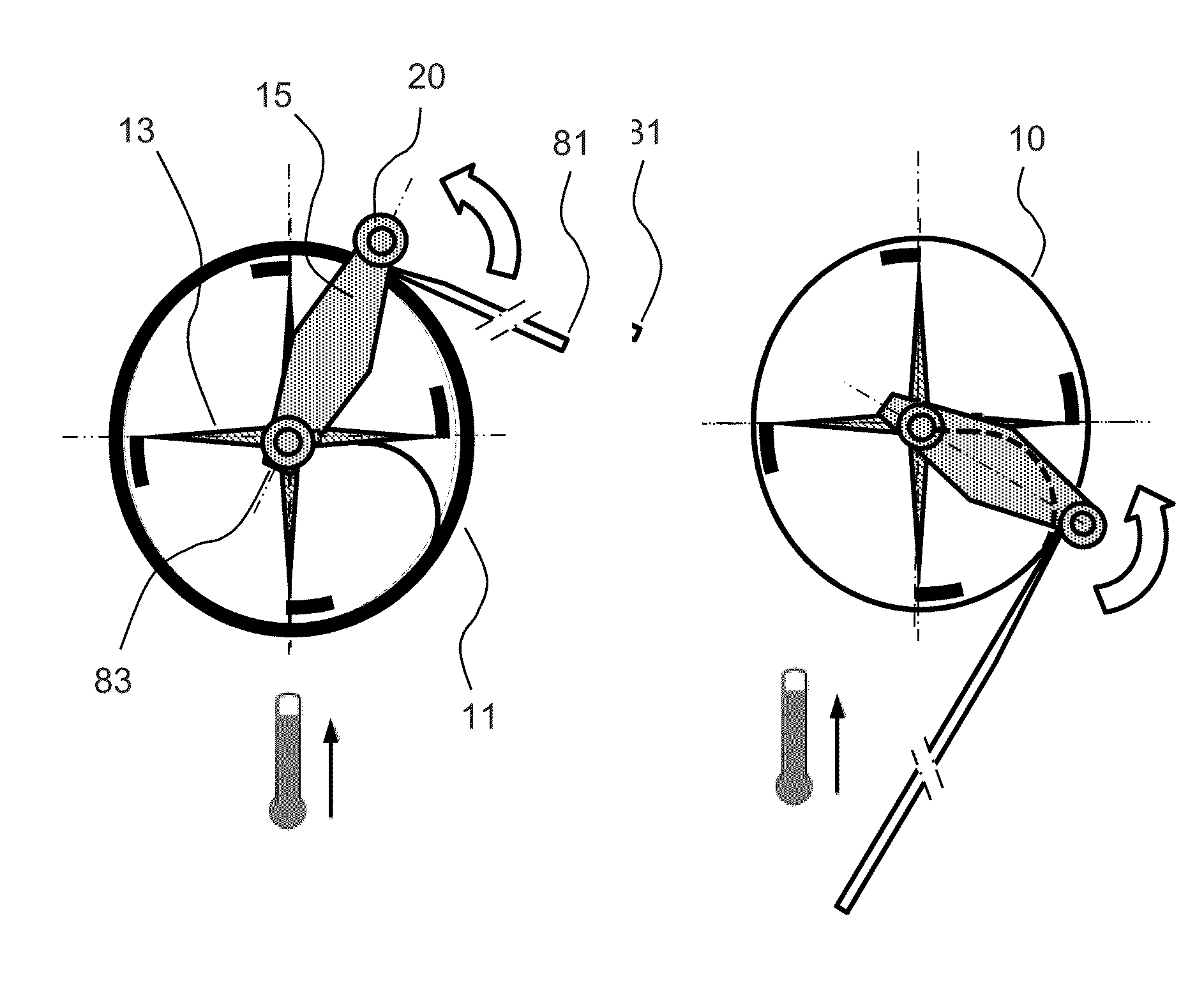
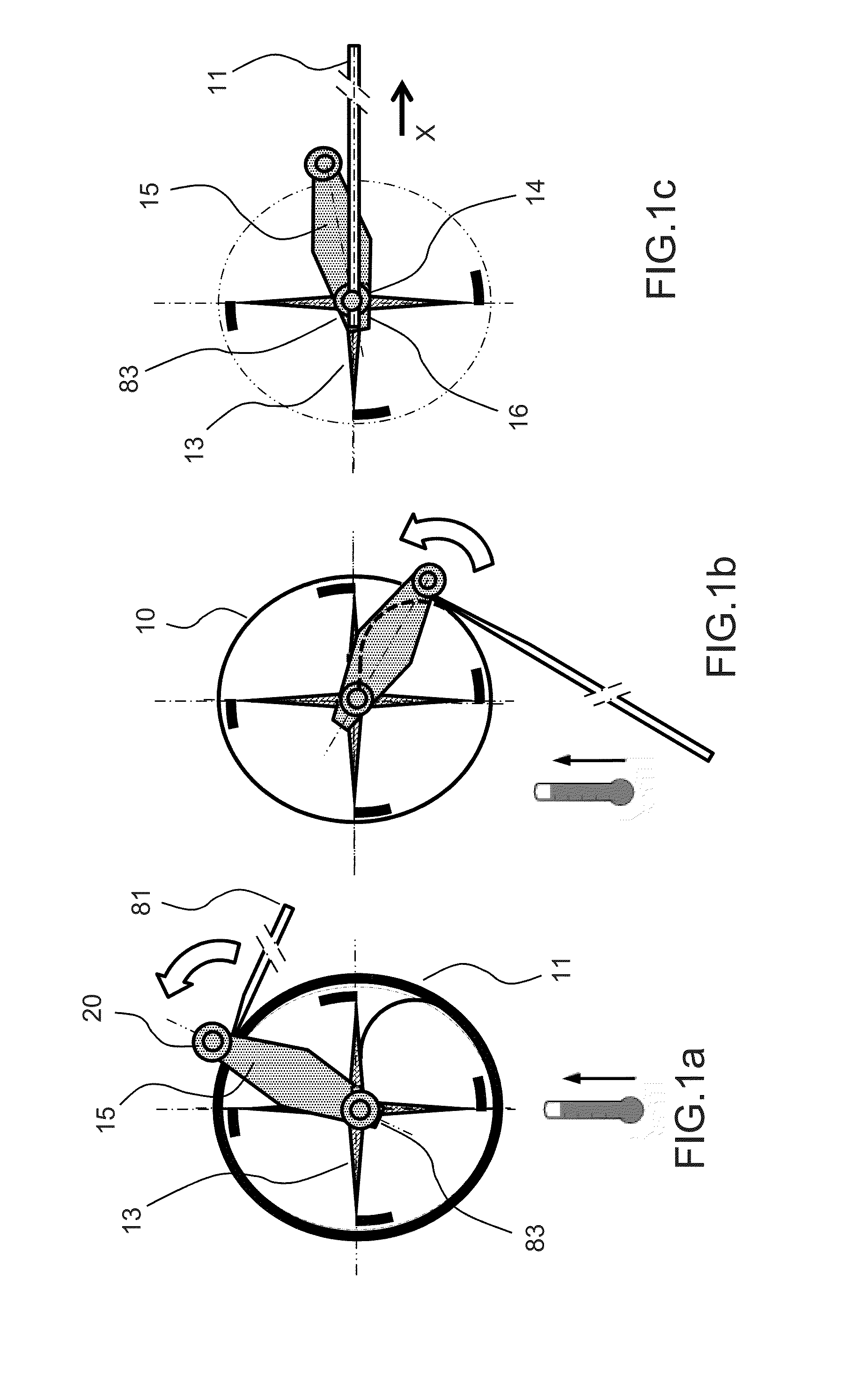
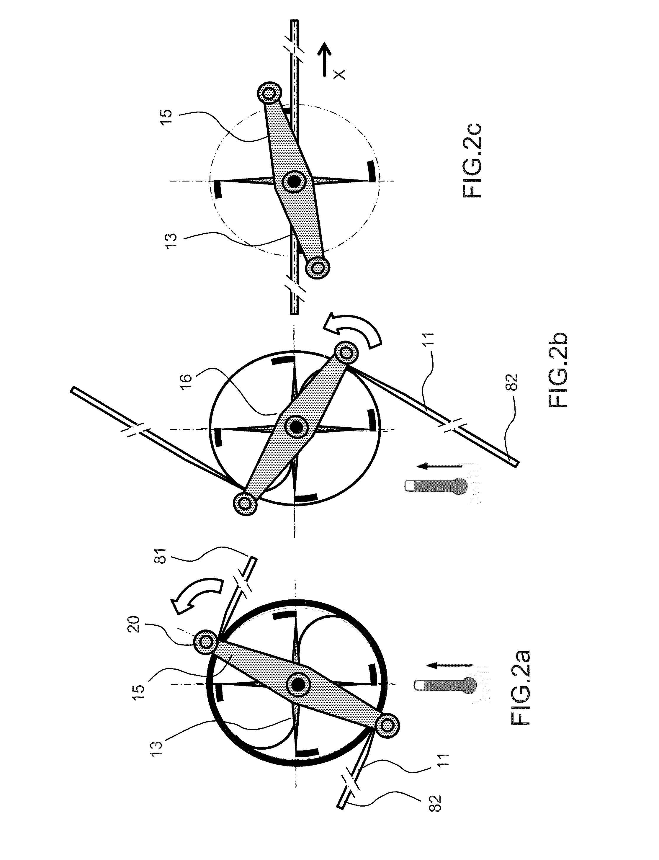
[0038]FIGS. 1a, 1b and 1c are three diagrams, in cross section on a plane perpendicular to a Z axis, of the deployable structure 10 according to the invention. The deployable structure 10 comprises a support 16 and a tape spring 11 fixed to the support 16, able to pass from a wound configuration in which it is wound about an axis Z into a deployed configuration along an unfurled axis X. The structure 10 further comprises a mobile arm 15 able to rotate with respect to the support 16 about the Z axis, able to form a first contact with the tape spring 11 so as to control the deployment of the tape spring 11. The first contact may be a point contact or alternatively a longitudinal contact along an axis substantially parallel to the Z axis, along the entire width of the tape spring 11 or just part of the width of the tape spring 11. Indeed without this contact the tape spring could deplo...


PUM


Abstract

A deployable structure comprises: a support, a tape spring fixed to the support, able to pass from a wound configuration wound about an axis Z, to a deployed configuration, and a mobile arm able to rotate with respect to the support about the Z-axis, able to form a first contact with the tape spring so as to control the deployment of the tape spring.

Description

CROSS-REFERENCE TO RELATED APPLICATION[0001]This application claims priority to foreign French patent application No. FR 1401712, filed on Jul. 25, 2014, the disclosure of which is incorporated by reference in its entirety.FIELD OF THE INVENTION[0002]The present invention relates to a tape spring deployable structure for a roll-up and deployable flexible structure. It applies notably to the field of space equipment that has to be deployed in orbit and more particularly to space equipment for satellites such as antennas, solar generators, heat screens, baffles or telescopes.BACKGROUND[0003]Structures deployable in space, of the solar generator type for example, are generally made up of rigid panels articulated to one another, these panels when in the stored position being stacked on top of one another. These structures have the advantage of having dynamic behaviour that is fully controlled but have the disadvantage of having a high inertia and a mass per unit area. Furthermore, rigid...

Claims


Application Information

Patent Timeline
IPC IPC(8): B64G1/44B64G1/22E04C3/00
CPCB64G1/222B64G1/44E04C3/005B65H75/28B65H75/285B65H75/4402B65H2701/373B65H2701/528B64G1/66
Inventor BAUDASSE, YANNICKVEZAIN, STEPHANEGUINOT, FRANCOIS
Owner THALES SA
Why Eureka
Try Eureka