Retractable tape spring in-building method for a deployable structure and tape spring deployable structure

a technology of deployable structure and tape spring, which is applied in the direction of transportation and packaging, aircrafts, and space occupation of rigid structures when in a stored position, which can solve the problems of high inertia and mass per unit area, uncontrollable deployment of monostable tapes, and inability to meet the needs of the customer, etc., to achieve the effect of optimizing the volume of the deployable structure, reducing the space, and being easy to produ

Active Publication Date: 2016-01-28
THALES SA
View PDF12 Cites 24 Cited by
  • Summary
  • Abstract
  • Description
  • Claims
  • Application Information

AI Technical Summary

Benefits of technology

[0008]The invention seeks to alleviate all or some of the problems mentioned hereinabove by proposing a retractable tape spring in-building method for a deployable structure, having the advantages of occupying very little space, being si

Problems solved by technology

These structures have the advantage of having dynamic behaviour that is fully controlled but have the disadvantage of having a high inertia and mass per unit area.
Furthermore, rigid structures when in a stored position occupy a significant amount of space under the cap of a launcher.
The deployment of monostable tapes is often disorganized and uncontrolled.
However, in both instances, when deployment is initiated it may be violent and generate shocks, which means to say that the entire tape spring may have a tendency to straighten out simultaneous

Method used


Image

  • Retractable tape spring in-building method for a deployable structure and tape spring deployable structure
  • Retractable tape spring in-building method for a deployable structure and tape spring deployable structure
  • Retractable tape spring in-building method for a deployable structure and tape spring deployable structure

Examples


Embodiment Construction

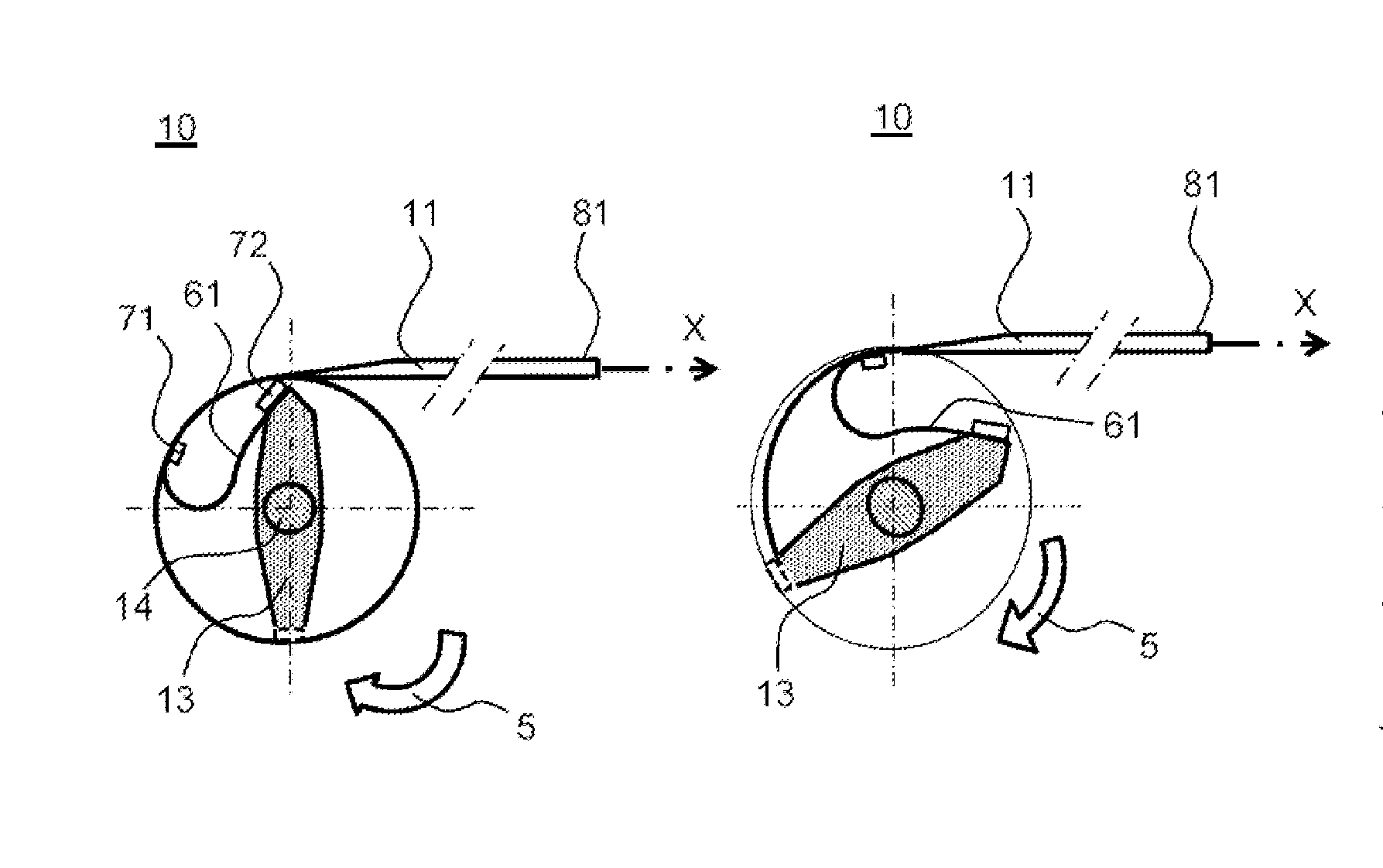
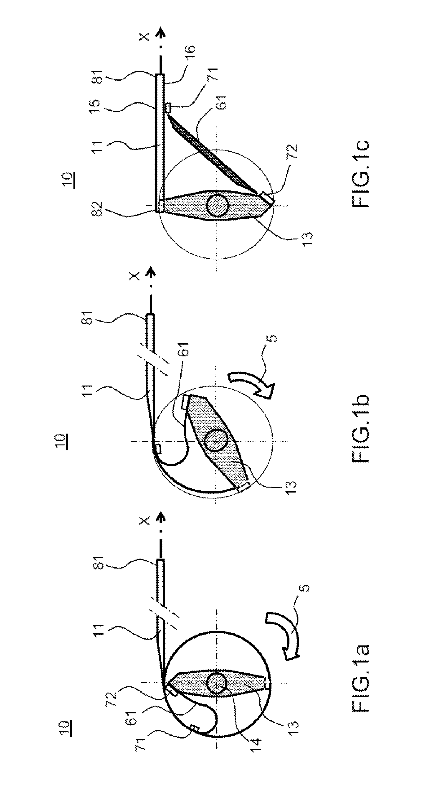
[0037]FIGS. 1a-1c illustrate, by way of three diagrams, and in cross section in a plane perpendicular to an axis Z, a deployable structure 10 with a main tape spring 11 according to the invention. The structure 10 comprises the main tape spring 11 extending in the deployed position along an axis X and comprises two ends 81, 82. The structure 10 comprises a secondary tape spring 61 which comprises two ends 71, 72. The deployable structure 10 also comprises a winding mandrel 13 which is carried by a shaft 14 along the axis Z perpendicular to the axis X. The main tape spring 11 is wound around the mandrel 13. A first end 82 of the main tape spring 11 is fixed on the mandrel 13. According to the invention, the retractable in-building method comprises the following steps:[0038]fixing a first end 71 of the secondary tape spring 61 some distance from a second end 81 of the main tape spring 11,[0039]fixing a second end 72 of the secondary tape spring 61 to the mandrel 13 at a point distinct...


PUM


Abstract

A retractable tape spring in-building method for a deployable structure comprising a main tape spring having an axis of deployment and of refurling substantially parallel to an unfurled axis X and comprising two ends, a secondary tape spring comprising two ends and a winding mandrel carried by a shaft parallel to an axis Z perpendicular to the axis X, the main tape spring being wound around the mandrel, a first end of the main tape spring being fixed to the mandrel, the method comprising the following steps: fixing a first end of the secondary tape spring a predefined distance away from a second end of the main tape spring, fixing a second end of the secondary tape spring on the mandrel. A deployable structure comprising a tape spring for a flexible structure is also provided.

Description

CROSS-REFERENCE TO RELATED APPLICATION[0001]This application claims priority to foreign French patent application No. FR 1401711, filed on Jul. 25, 2014, the disclosure of which is incorporated by reference in its entirety.FIELD OF THE INVENTION[0002]The present invention relates to a retractable tape spring in-building method for a deployable structure. It also relates to a deployable structure comprising a tape spring. It applies notably to the field of space equipment that has to be deployed in orbit and more particularly to space equipment for satellites such as antennas, solar generators, heat screens, baffles or telescopes.BACKGROUND[0003]Structures deployable in space, of the solar generator type for example, are generally made up of rigid panels articulated to one another, these panels when in the stored position being stacked on top of one another. These structures have the advantage of having dynamic behaviour that is fully controlled but have the disadvantage of having a ...

Claims


Application Information

Patent Timeline
IPC IPC(8): E04C3/00B64G1/22
CPCB64G1/222E04C3/005B64G1/44B64G1/503B64G1/66
Inventor BAUDASSE, YANNICKVEZAIN, STEPHANESTANEK, DIDIER
Owner THALES SA
Why Eureka
Try Eureka