Monitoring System

a monitoring system and monitoring method technology, applied in the field of systems and methods for non-intrusive monitoring, can solve problems such as waste of resources, disassembly and assembly of equipment, and overconsumption of resources

Active Publication Date: 2016-01-28
REMONI APS
View PDF12 Cites 19 Cited by
  • Summary
  • Abstract
  • Description
  • Claims
  • Application Information

AI Technical Summary

Benefits of technology

[0070]It may be an advantage that a user interface has remote access to the system.
[0071]It may be an advanta

Problems solved by technology

Waste and overconsumption of resources are a major concern in modern society, because it leads to both environmental and economic problems.
A significant part of the wasted resources origins from dysfunctional or inefficient devices.
Dysfunctional devices may lead to waste of resources because the intended production is damaged or even lost, whereas inefficient devices may lead to overconsumption of resources to obtain the desired production.
From industrial production it is well known that present and emerging problems can be identified, and overconsumption of resources reduced, by continuous monitoring at level of the single production devices.
The challenge of the present systems is, however, that the expenses to install and operate the entire set of needed specialized technologies limit the areas of use.
Moreover, such monitoring systems are often complicated to retrofit at existing device installations, and difficult to fit acceptable into the designs.
This technique, however, is unable to handle a complex electrical setup, and to overcome the challenge it has been proposed to add

Method used


Image

  • Monitoring System
  • Monitoring System
  • Monitoring System

Examples


Embodiment Construction

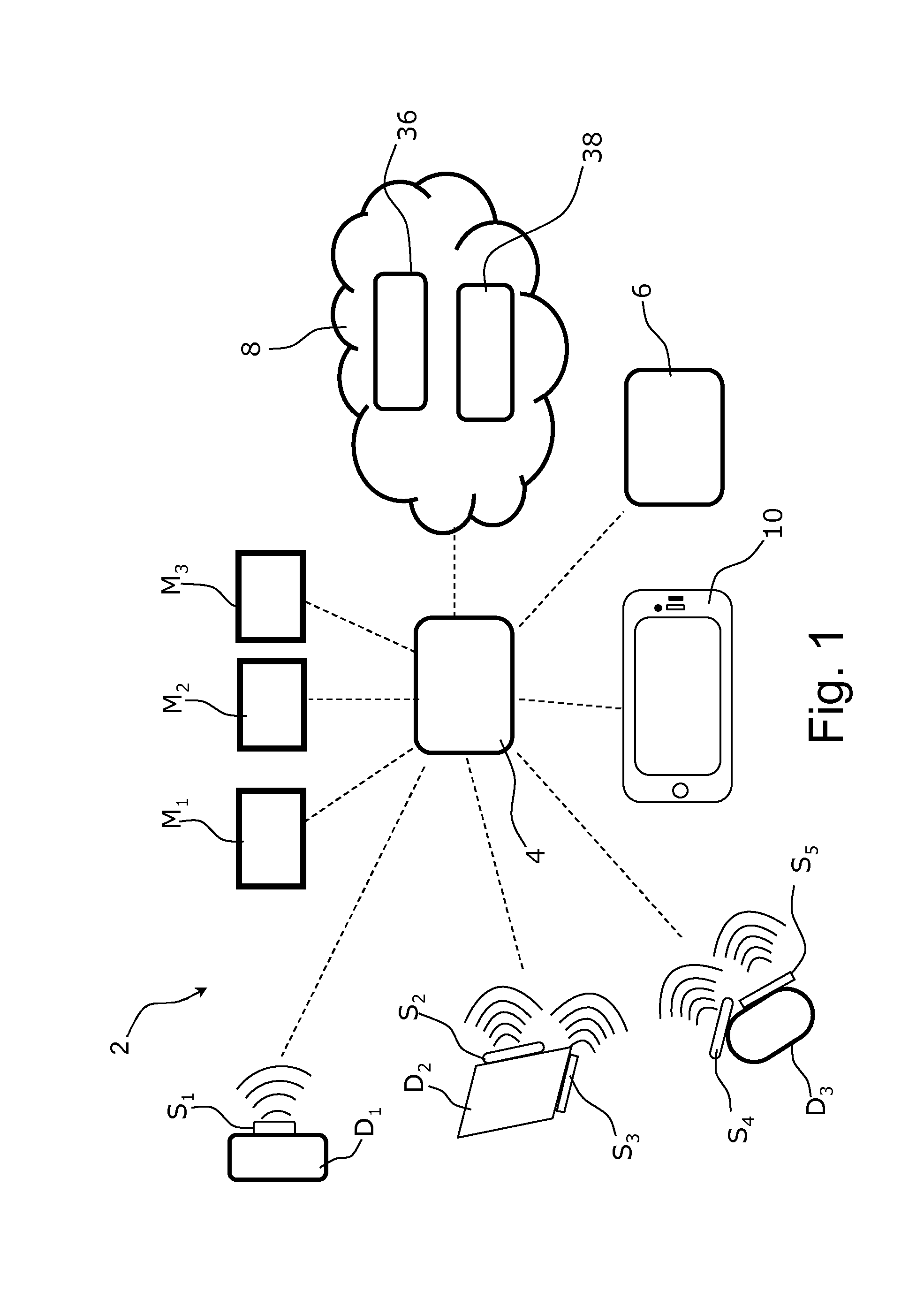
[0078]Referring now in detail to the drawings for the purpose of illustrating preferred embodiments of the present invention, a system 2 according to the present invention is illustrated in FIG. 1.

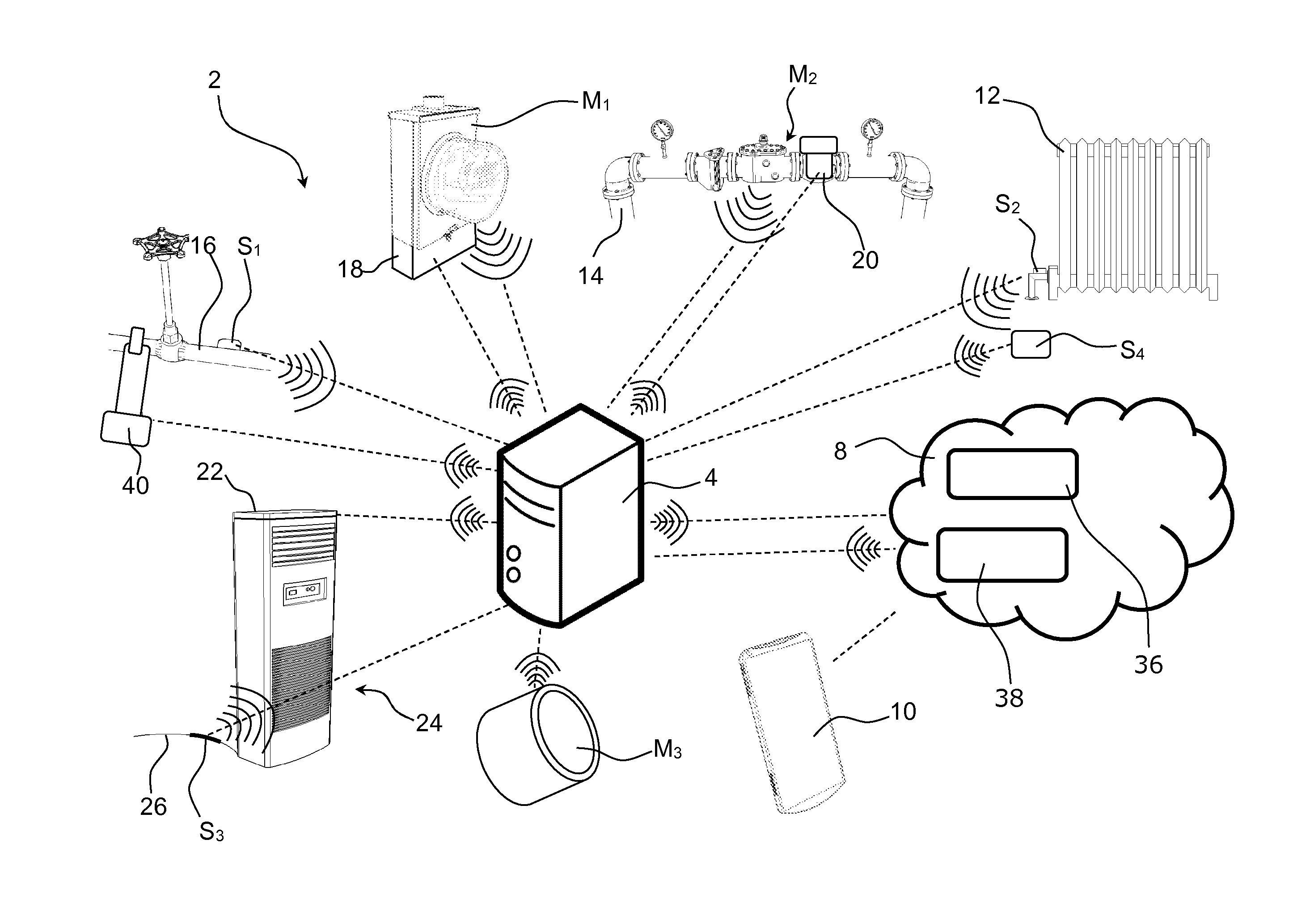
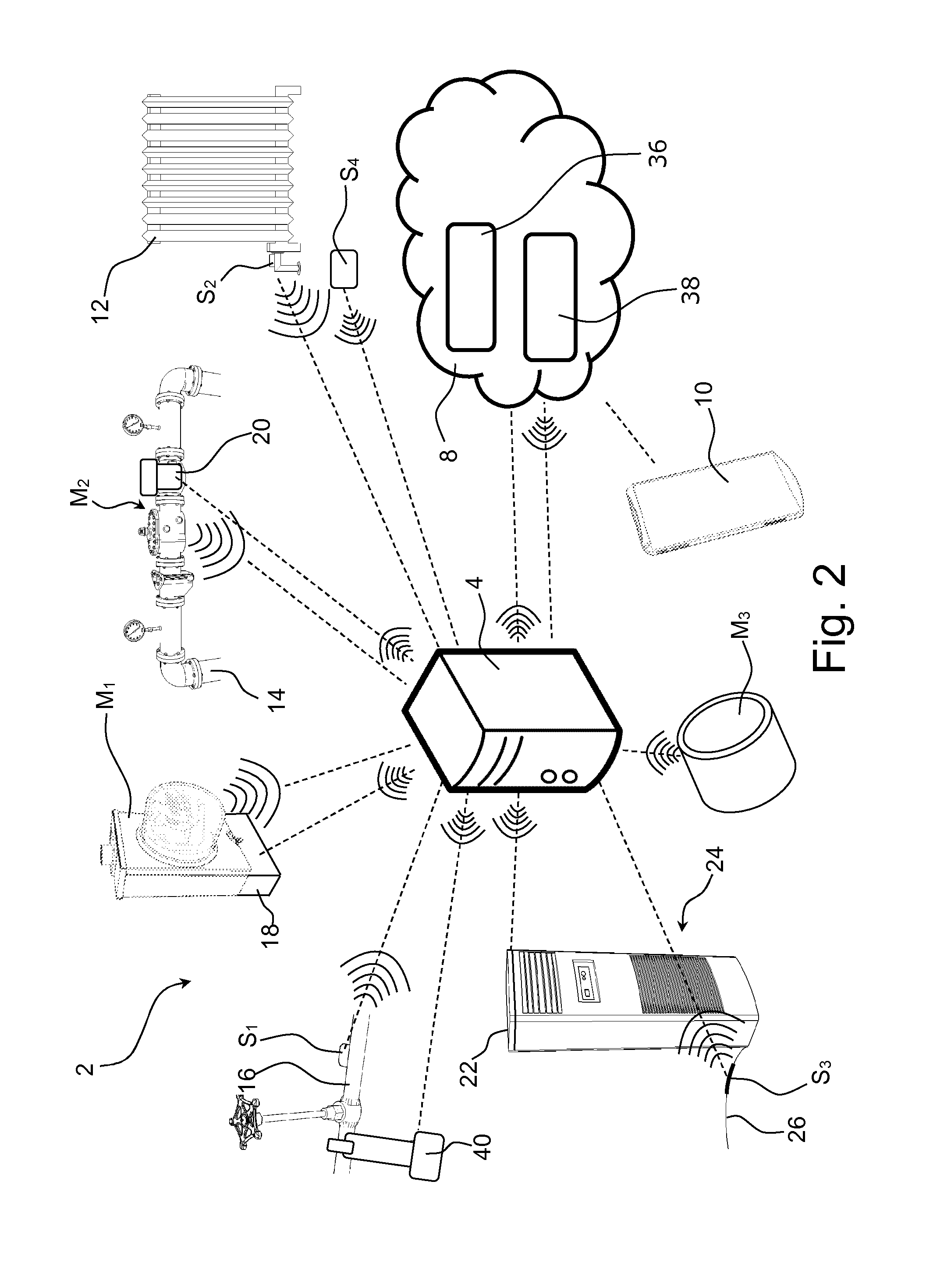
[0079]FIG. 1 is a schematic view of a system 2 according to the invention. The system 2 includes a first sensor S1 configured to monitor a first device D1 to which the first sensor S1 is attached. The system 2 also includes two further sensors (S2 and S3) which are configured to monitor a second device D2. The system 2 moreover includes two further sensors (S4 and S5) which are configured to monitor a third device D3. The sensors S1, S2, S3, S4, S5 are configured to communicate wirelessly with a router 4.

[0080]The system 2 includes meters (M1 and M2) that are configured to communicate with the router 4 that is configured to communicate wirelessly with a cloud service 8. The router 4 is communicating wirelessly with a user interface 10 represented by a smartphone 10. The router 4 is also co...


PUM


Abstract

A system (2) for monitoring resource flows at a number of devices (D1, D2, D3) includes a receiving unit (4) which receives data from a number of sensors (S1, S2, S3, S4, S5) configured to detect the flow rate and/or the change in the flow rate at device level, and a number of meters (M1, M2, M3) configured to measure the flow for at least a part of the devices (D1, D2, D3). The system (2) has a calculation module (8) configured to receive information from the sensors (S1, S2, S3, S4, S5) and the meters (M1, M2, M3), and the calculation module (8) includes a mathematical statistical model (38) configured to estimate and/or predict flow of resource and/or performance (e.g., activity) of at least a selection of the devices (D1, D2, D3).

Description

[0001]This application is a Continuation of, and claims priority under 35 U.S.C. §120 to, International Application No. PCT / DK2014 / 000019, filed 23 Apr. 2014, which claims priority therethrough under 35 U.S.C. §§119, 365 to Danish App. No. PA 2013 00249, filed 26 Apr. 2013, the entireties of which are incorporated by reference herein.BACKGROUND[0002]1. Field of Endeavor[0003]The present invention generally relates to a system and a method for non-intrusive monitoring. The present invention more particularly relates to a system and a method for non-intrusive monitoring at device level to overview technical installations to identify devices that cause loss of resources.[0004]2. Brief Description of the Related Art[0005]Waste and overconsumption of resources are a major concern in modern society, because it leads to both environmental and economic problems. A significant part of the wasted resources origins from dysfunctional or inefficient devices. Dysfunctional devices may lead to wa...

Claims


Application Information

Patent Timeline
IPC IPC(8): G01F1/56G06F17/18G06F17/50
CPCG01F1/56G06F17/5009G06F17/18G01D4/02G01D2204/12G01D2204/14G06F30/20Y02B90/20Y04S20/30
Inventor MADSEN, BO, ESKEROD
Owner REMONI APS
Why Eureka
Try Eureka