
Large format 3D printing augmented with 3D scanning and anomoly tracking feedback

Active Publication Date: 2018-12-20
2679667 ONTARIO INC
View PDF0 Cites 15 Cited by
  • Summary
  • Abstract
  • Description
  • Claims
  • Application Information

AI Technical Summary

Benefits of technology

The patent text describes a system and method for printing and scanning objects using a robot and various components. The system can break down sub-components to form an unlimited size print volume, track the position of each component, and combine coordinate systems. The method and apparatus allow for more accurate and efficient printing using a lower-cost industrial robot, as well as printing onto non-planar surfaces and providing automatic visual feedback. The technical effects include improved accuracy and flexibility in printing and scanning.

Problems solved by technology

Further, the method includes repositioning of the components to incrementally increase the size of the printed object without practical limits beyond the printing envelope of the 3D printer and the measurement volume of the tracking system.

Method used


Image

  • Large format 3D printing augmented with 3D scanning and anomoly tracking feedback
  • Large format 3D printing augmented with 3D scanning and anomoly tracking feedback
  • Large format 3D printing augmented with 3D scanning and anomoly tracking feedback

Examples


second embodiment

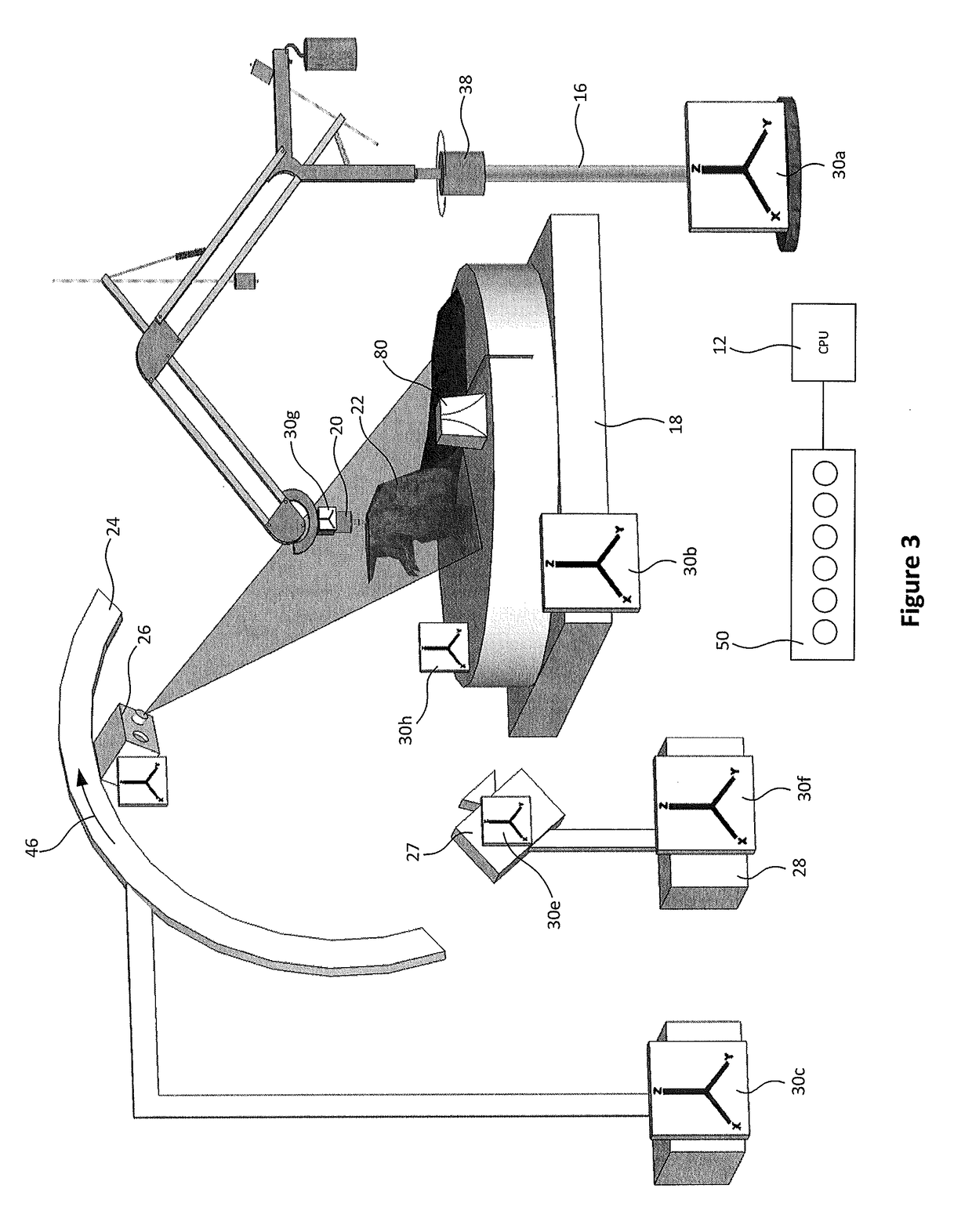
[0063]Turning to FIG. 3, a 3D printing system is shown. In this embodiment, the 6D tracking system 50 is a magnetic system which does not have line of sight requirements to determine the coordinate systems of the components. The magnetic tracking system 50, of which there are several known in the art, is adapted to return the pose of each component within the global coordinate system as defined by tracker 30h. The 6D magnetic tracking system 50 is preferably selected such that it has greater accuracy than the industrial robot 16 and platform 18. In the current embodiment, the trackers 30 may be three orthogonally wound coils. A frame of reference magnetic transmitter 80 produces a magnetic field and induces current in the three coils of the orthogonal windings of each of the trackers 30 to assist the magnetic tracking system 50 to determine the pose of each of the components. As will be understood, the tracking system 50 can determine the pose of the trackers 30 from these induced c...

third embodiment

[0064]Turning now to FIG. 5, a printing system is shown. In this embodiment, there is no external 6D tracking system whereby the components of the 3D printer are physically aligned to each other by connecting members 82 to a plurality of mating sockets 84 in each of the components. The various sockets 84 are distributed about each of the components. The connecting members 82 can be made of a fixed length or can be adapted to be adjustable. If adjustable, the length can have discrete increments or infinite settings. The length can be mechanically indicated from a Vernier scale or like; or automatically read by the control computer 12 if adapted with length detection circuitry, as is known in the art. In one embodiment, the connecting members 82 have different lengths and a plurality of sockets 84 such that the components of the system are able to be flexibly relocated as needed. As will be understood, there are only finite combinations of configurations available. Although this is a ...


PUM


Abstract

The disclosure is directed at a system, apparatus and method for 3D printing an object using an industrial robot; such object is larger and may be more accurate than the print volume and accuracy of the industrial robot that is performing the print. The system is further capable of scanning the irregular 3D surface of the printing platform in which to create the 3D object and adapt the toolpath to print on this surface. The system is further capable of scanning the 3D surface of a specimen that is larger than the print volume of the industrial robot and make a scaled copy larger or smaller. The system is also capable of monitoring the quality of the object being printed while the print is in process.

Description

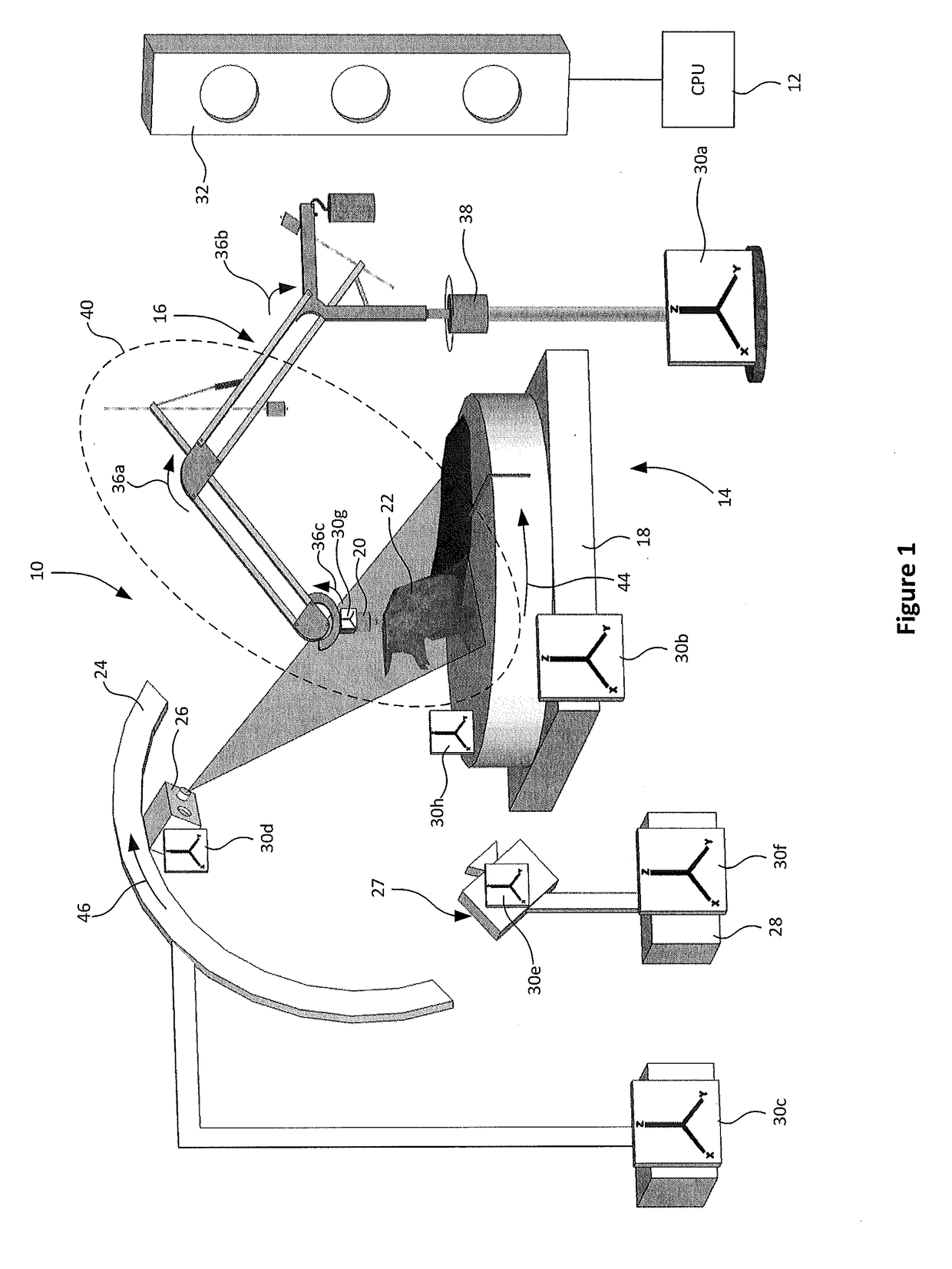
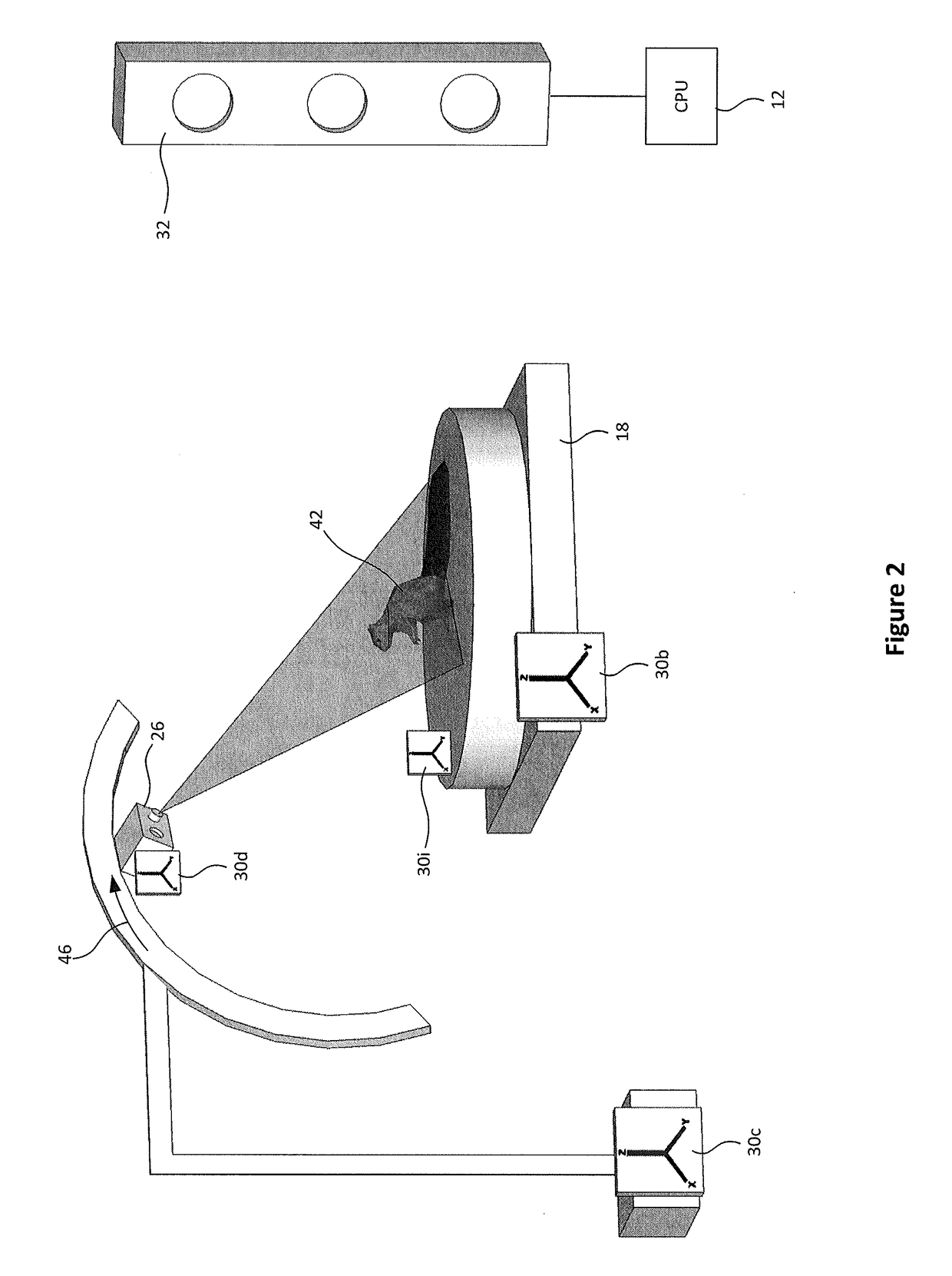
CROSS-REFERENCE TO OTHER APPLICATIONS[0001]This application claims the benefit of U.S. Patent Application No. 62 / 270,122, filed Dec. 21, 2015, which is incorporated herein by reference.FIELD OF THE DISCLOSURE[0002]This disclosure relates generally to the field of additive manufacturing, and more specifically, to a method and apparatus for large format three-dimensional (3D) printing.Background to the Disclosure[0003]As computers within manufacturing have advanced, so have methods of producing three-dimensional (3D) computer models and the ability to manufacture these models into printed objects using rapid prototyping techniques. Additive manufacturing is one of these techniques.[0004]It is well known in the art how to produce fused deposition printers typically using a Cartesian style industrial robot. An example of this type of robotic printer is MakerBot™ Industries' Replicator. When printing an object, these robotic printers typically apply a very thin layer of material in the X...

Claims


Application Information

Patent Timeline
IPC IPC(8): B33Y30/00B33Y10/00G06F17/50B33Y50/02B25J9/16
CPCB33Y30/00B33Y10/00G06F17/50B33Y50/02B25J9/1697G01B11/002G01B11/24G01B11/2518G01S17/42G01S17/74G01S17/88G01S17/89B29C64/232B29C64/241B29C64/393B29C64/236B29C64/118G06F30/00
Inventor GIBSON, CHRISTOPHER JOHN ELMERLEIS, PETER ELDON
Owner 2679667 ONTARIO INC
Learn More