Lens Moving Apparatus

a technology of moving apparatus and moving parts, applied in the field of moving parts, can solve problems such as noise generation and oscillation phenomenon, and achieve the effect of eliminating oscillation phenomenon and reducing nois

Active Publication Date: 2016-01-28
LG INNOTEK CO LTD
View PDF16 Cites 18 Cited by
  • Summary
  • Abstract
  • Description
  • Claims
  • Application Information

AI Technical Summary

Benefits of technology

[0009]Embodiments provide a lens moving apparatus which is designed to reduce no

Problems solved by technology

However, such a conventional lens moving apparatus has drawbacks as follows:
When the connection portion is configured to have a specific pattern having a plurality of bent portions, the pl

Method used


Image

  • Lens Moving Apparatus
  • Lens Moving Apparatus
  • Lens Moving Apparatus

Examples


first embodiment

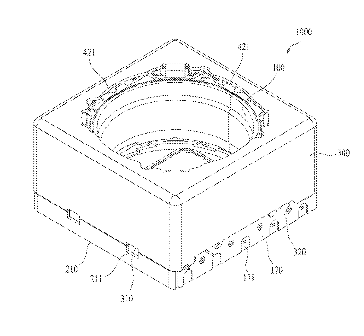
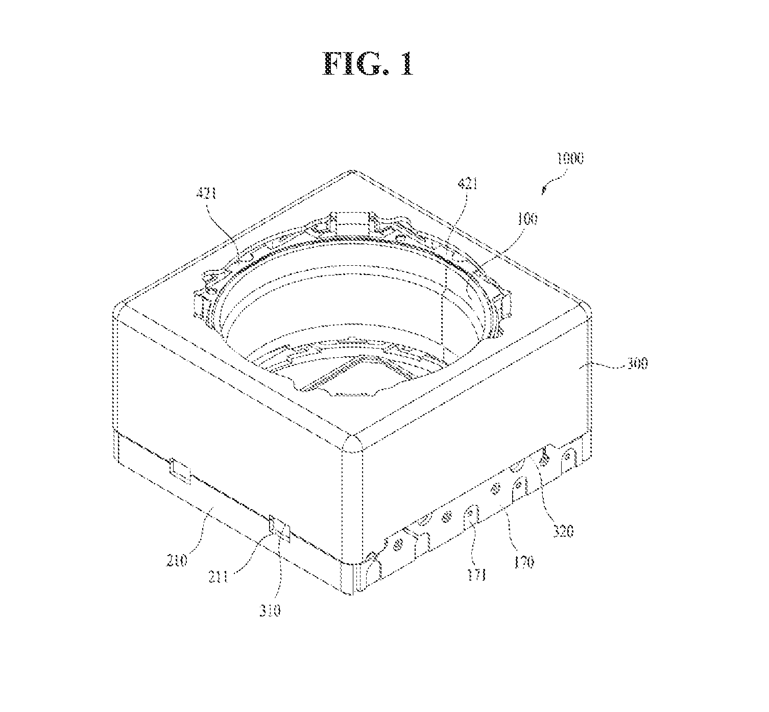
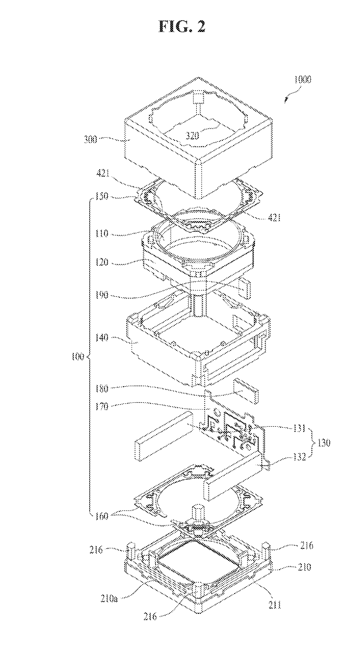
[0052]FIG. 1 is a schematic perspective view of the lens moving apparatus. FIG. 2 is an exploded perspective view of the lens moving apparatus shown in FIG. 1. FIG. 3 is a schematic perspective view of the lens moving apparatus shown in FIG. 1 from which a cover member is removed. FIG. 4 is a schematic plan view of FIG. 3. FIG. 5 is a schematic perspective view of a housing in the lens moving apparatus shown in FIG. 1. FIG. 6 is a schematic perspective view of the housing when viewed at an angle different from that in FIG. 5. FIG. 7 is a schematic bottom perspective view of the housing in the lens moving apparatus shown in FIG. 1. FIG. 8 is a schematic exploded perspective view of the housing in the lens moving apparatus shown in FIG. 1. FIGS. 9A to 9C are schematic plan views of an upper elastic member in the lens moving apparatus shown in FIG. 1. FIGS. 10A and 10B are schematic plan views of a lower elastic member in the lens moving apparatus shown in FIG. 1. FIGS. 11A to 11C are ...

second embodiment

[0155]FIG. 25 is a view showing the relationship between gain and phase in the lens moving apparatus.

[0156]In this embodiment, when the dampers and the parasitic regions in the connection portions of the upper or lower elastic member are provided, the peak value may be decreased and frequency changing may occur, thus suppressing noise and preventing an oscillation phenomenon during driving of the vibration motor or the like, as indicated by “A” and “B”.

[0157]FIGS. 26A to 26C are views showing an oscillation phenomenon occurring when gain is gradually increased in the second embodiment of the lens moving apparatus, and FIG. 27 is a view showing that, when the dampers and the parasitic regions in the connection portions of the upper or lower elastic member are provided, frequency properties are changed, thus preventing an oscillation phenomenon.

[0158]The lens moving apparatus, which is constructed as described above, may include the lens barrel coupled to the bobbin, the image sensor ...


PUM


Abstract

Embodiments provide a lens moving apparatus including a housing for supporting a first magnet, a bobbin including a coil disposed on an outer surface thereof and inside the first magnet so as to move in the housing in a first direction parallel to an optical axis by electromagnetic interaction between the first magnet and the coil, and upper and lower elastic members, each of which is provided at the bobbin and the housing and includes an inner frame coupled to the bobbin and an outer frame coupled to the housing, wherein at least one of the upper and lower elastic members is constituted by a printed circuit board.

Description

CROSS REFERENCE TO RELATED APPLICATIONS[0001]This application claims the benefit under 35 U.S.C. §119 of Korean Patent Application Nos. 10-2014-0093861 and 10-2014-0093934, filed Jul. 24, 2014, which are herein incorporated by reference in their entirety.TECHNICAL FIELD[0002]Embodiments relate to a lens moving apparatus.BACKGROUND[0003]In recent years, IT products equipped with subminiature digital cameras such as, for example, cellular phones, smartphones, tablet PCs, and notebook computers, have actively been developed.[0004]IT products equipped with conventional subminiature digital cameras incorporate a lens moving apparatus for aligning the focal distance of a lens by adjusting the distance between the lens and an image sensor, which converts outside light into a digital image.[0005]A lens moving apparatus includes an upper elastic member and a lower elastic member. Each of the upper and lower elastic member may include an inner frame coupled to a bobbin, an outer frame coupled...

Claims


Application Information

Patent Timeline
IPC IPC(8): G02B7/04
CPCG02B7/04G02B7/08G02B27/646
Inventor PARK, SANG OKLEE, SEONG MINLEE, JUN TAEK
Owner LG INNOTEK CO LTD
Why Eureka
Try Eureka