
Methods and apparatus to facilitate proximity detection and location tracking

a technology of applied in the field of health care environments, can solve the problems of increasing recovery time, patient harm, loss of hospital's and its staff's capacity to serve, etc., and achieve the effect of facilitating facilitating proximity detection and location tracking

Active Publication Date: 2016-01-28
GENERAL ELECTRIC CO
View PDF9 Cites 110 Cited by
  • Summary
  • Abstract
  • Description
  • Claims
  • Application Information

AI Technical Summary

Benefits of technology

The patent describes a method, apparatus, and machine-readable storage medium for detecting the presence and location of badges and assets in an environment. The badges collect messages with signal strength and a timestamp, and the system assigns a location to the badge based on the messages and a timeline. The system can also identify assets in the messages and update the location of the asset based on its relative proximity to the badge. The update takes into account the change in location between the first and second times the asset is detected. The technical effect of this patent is improved accuracy in identifying and tracking the location of badges and assets in an environment.

Problems solved by technology

Adverse events that occur in hospitals, such as hospital-acquired infections, lost or missing assets, etc., result in patient harm, increased recovery time, loss of a hospital's and its staff's capacity to serve, unreimbursed healthcare costs, and, generally, increased healthcare costs.
One of the main causes of these events is non-adherence to protocols.
However, this is an expensive and time-consuming solution because it requires pulling power and data cabling to all the required locations.
Typical RFID systems have a tolerance of approximately plus-or-minus ten feet, further limiting their range.
RFID and IR-based sensors, though, are highly susceptible to drift due to interference in the environment (e.g., a patient room) and cross talk between locations that are physically separated, but have a line of sight between them (e.g., two patient rooms across the hall from each other).

Method used


Image

  • Methods and apparatus to facilitate proximity detection and location tracking
  • Methods and apparatus to facilitate proximity detection and location tracking
  • Methods and apparatus to facilitate proximity detection and location tracking

Examples


example reader

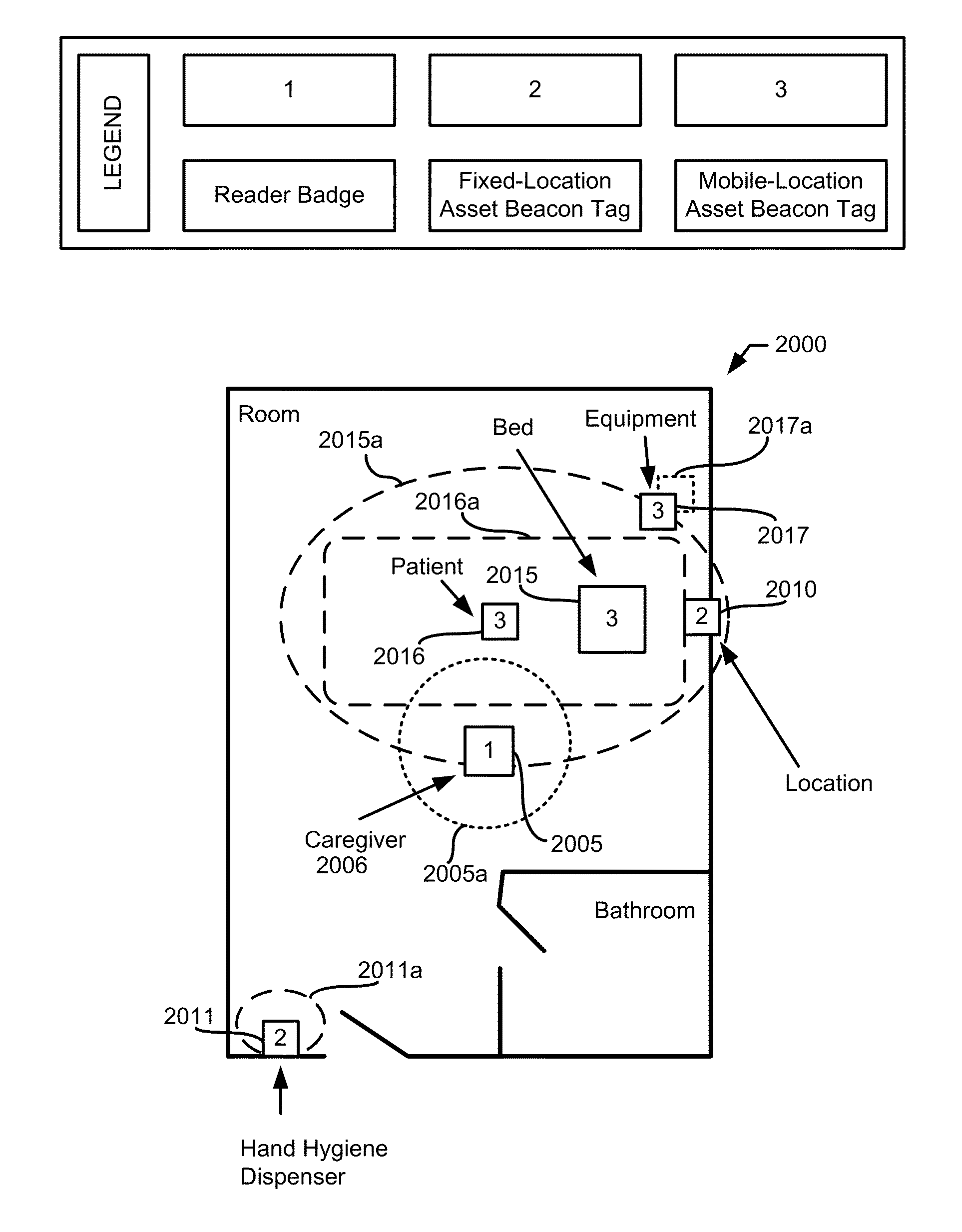
[0045 badges disclosed herein include a proximity engine to process the beacon messages and determine distance from the source (e.g., the beacon tag that broadcast the corresponding beacon message). For example, a hospital room may include a first beacon tag affixed to a door, a second beacon tag affixed to an infusion pump, a third beacon tag affixed to a bed, and a fourth beacon tag included in a patient tag (e.g., a disposable bracelet including patient identification information such as name, sex, date of birth information). As the caregiver moves about the hospital room, the reader badge may receive beacon messages from each of the beacon tags. The proximity engine can determine the RSSI strength for each of the beacon messages and associate RSSI strength with a respective beacon tag.

[0046]In some examples, the proximity engine determines which beacon tags are proximate (e.g., near or closely located) to the reader badge. For example, the proximity engine can compare the RSSI s...


PUM


Abstract

Methods, apparatus, systems and articles of manufacture are disclosed to facilitate proximity detection and location tracking. An example method includes receiving messages collected by a badge in an environment, the messages including signal strength and a timestamp. The example method also includes assigning a location in the environment to the badge based on a first subset of the messages. The example method also includes identifying an asset in a second subset of the messages. The example method also includes updating a current location associated with the asset based on a relative proximity of the asset to the badge, wherein the current location corresponds to a first time and the updated location corresponds to a second time, and wherein a change in location between the current location and the updated location indicates movement of the asset in the environment.

Description

RELATED APPLICATION[0001]This patent claims the benefit of U.S. Provisional Patent Application Ser. No. 62 / 029,252, filed Jul. 25, 2014, entitled “HOSPITAL TRACKING NETWORK.” U.S. Provisional Patent Application Ser. No. 62 / 029,252 is hereby incorporated by reference herein in its entirety.FIELD OF THE DISCLOSURE[0002]This disclosure relates generally to healthcare environments, and, more particularly, to methods and apparatus to facilitate proximity detection and location tracking.BACKGROUND[0003]Industrial settings such as hospitals, construction sites, retail centers, etc. can be chaotic environments. A hospital is used herein as an example of an industrial setting. A hospital stay, for even straight-forward care, involves hundreds of healthcare resources. Healthcare resources include people (e.g., doctors, nurses, staff, etc.), processes and assets. The effectiveness of a healthcare system can be determined by the interaction between the healthcare resources. Adverse events that ...

Claims


Application Information

Patent Timeline
IPC IPC(8): G06K7/10H04W4/029H04W4/02H04W4/80
CPCG06K7/10425G16Z99/00G06Q10/087G16H40/63G16H40/20G16H40/40H04W4/029H04W4/80H04W4/025H04W4/02G01S5/0289G01S5/0284H04L67/52H04W84/12H04L43/106
Inventor GOOD, BRANDON STEPHENTHEURER, CHARLES BURTONLIU, SHAOPENGWALLACE, ROBERT LEE
Owner GENERAL ELECTRIC CO
Learn More