Distributed Reactive Power Control in Power Distribution Systems

a technology of distributed reactive power control and power distribution system, which is applied in the direction of reactive power compensation, computer control, instruments, etc., can solve the problems of system-wide voltage violations, affecting the performance of overall voltage regulation, and the life of equipment could be dramatically reduced

Inactive Publication Date: 2016-01-28
MITSUBISHI ELECTRIC RES LAB INC
View PDF2 Cites 11 Cited by
  • Summary
  • Abstract
  • Description
  • Claims
  • Application Information

AI Technical Summary

Benefits of technology

[0010]Some embodiments of the invention are based on a realization that it is possible, for any monitoring controller to locally determine the amount of reactive power required to compensate the voltage violation on the monitored bus using only local information avai

Problems solved by technology

Without proper regulation, a large number of DERs in distribution systems can cause system-wide violations of the voltage.
However, existing equipment is not inherently designed to handle the variability introduced by DERs, and the lifetime of the equipment could be dramatically reduced due to the increased number of o

Method used


Image

  • Distributed Reactive Power Control in Power Distribution Systems
  • Distributed Reactive Power Control in Power Distribution Systems
  • Distributed Reactive Power Control in Power Distribution Systems

Examples


Embodiment Construction

[0026]Distribution Systems and Three-Phase Reactive Power Control

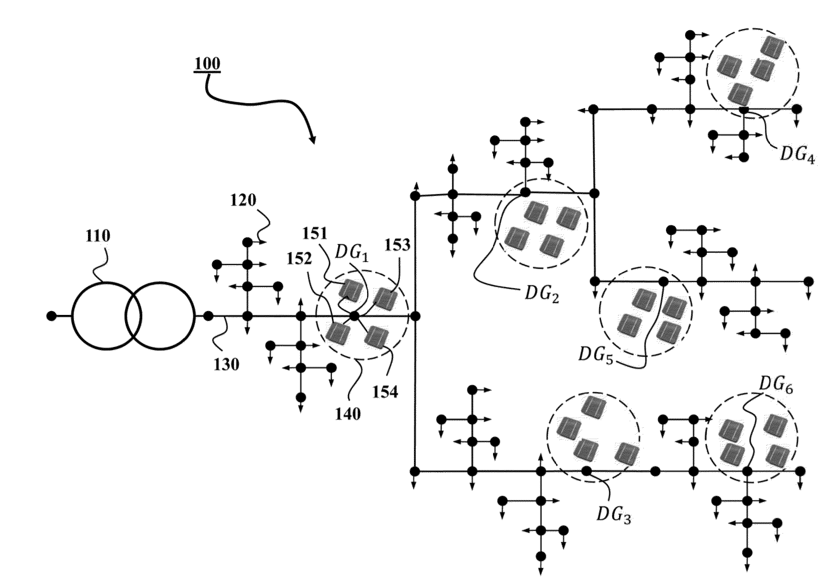
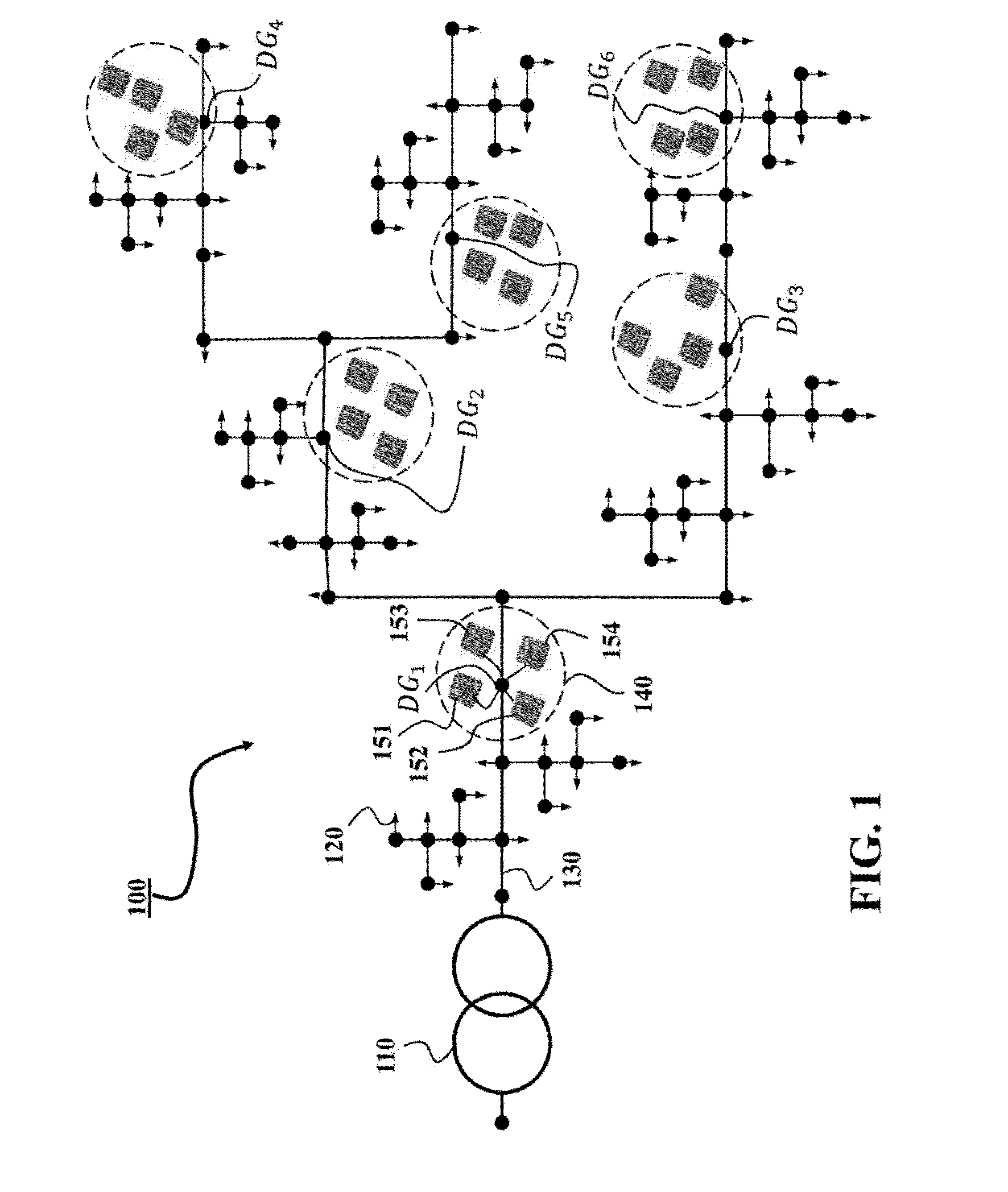
[0027]FIG. 1 shows an example of a power distribution system 100 that includes a distribution substation in which a three-phase transformer 110 receives electric power from power transmission systems, and provides the power to downstream loads 120 through power lines 130. The distribution system can include a set of buses connected with distributed energy resources (DERs). Those buses, e.g., a bus DG1, a bus DG2, a bus DG3, a bus DG4, a bus DG5 and a bus DG6, are referred herein as DER buses. The power distribution system 100 also includes DER controllers, such as a DER controller 140, arranged on corresponding DER buses and operatively connected with a set of DERs. For example the DER controller 140 of the DER bus DG1 is connected with four photovoltaic units, e.g., the DER units 151, 152, 153 and 154. The loads, the DERs and the power lines can be of single-phase, double-phase, or three-phase. The distribution system...


PUM


Abstract

A method regulates voltages of a power distribution system that includes a substation transformer, at least one distributed energy resource (DER) for generating reactive power into the power distribution system, at least one DER controller operatively connected to the DER for controlling an amount of the generated reactive power, and a monitoring controller for monitoring a voltage violation on at least one phase of a monitored bus. The method determines an amount of reactive power required to compensate a voltage violation on the monitored bus using equivalent impedances of a path of the power distribution system between the substation transformer and the monitored bus and a shift of phase angle on the path, and transmits a request to provide the reactive power to compensate the voltage violation.

Description

FIELD OF THE INVENTION[0001]The present invention relates generally to power distribution systems, and more particularly to distributed reactive power control of the power distribution systems using distributed energy resources (DERs).BACKGROUND OF THE INVENTION[0002]Compared with conventional utility-scale generation sources, such as fossil-fuel-fired and hydro power plants, the capacity of a DER is relatively small, but the location of DERs can be widely spread across the system. Examples of DERs include diesel engine-generators, wind turbines, photovoltaic units, fuel cells, and energy storages.[0003]The DERs can be conveniently connected to an alternating current (AC) distribution grid. A DER can be used to generate an active power (symbolized as P), a reactive power (symbolized as Q), or combination of both. The reactive power generated by the DER influences the voltages of the grid. Specifically, the amount of reactive power is proportional to the voltages in the grid, i.e., w...

Claims


Application Information

Patent Timeline
IPC IPC(8): H02J3/16G05B15/02G05F1/10G06F17/16H02J3/18H02J13/00
CPCH02J3/16H02J3/18G06F17/16G05B15/02G05F1/10H02J13/0006H02J3/381Y02E40/30H02J2300/10Y04S10/12Y04S10/16Y02E40/70Y02E60/00
Inventor SUN, HONGBO
Owner MITSUBISHI ELECTRIC RES LAB INC
Why Eureka
Try Eureka