Systems and Methods of Providing Enhanced Electric Fence Diagonstics

a technology of enhanced electrical fences and diagnostics, applied in the field of electric fences, can solve the problems of limited power output range, very little feedback, and current conventional energizers

Active Publication Date: 2016-01-28
ELECTRIC GUARD DOG
View PDF1 Cites 13 Cited by
  • Summary
  • Abstract
  • Description
  • Claims
  • Application Information

AI Technical Summary

Problems solved by technology

Unfortunately, current conventional energizers have several drawbacks.
These drawbacks include that they provide no guidance to locate a fault in the fence on a very large premise, they provide very little feedback, if any, about the condition of a fence or energizer prior to a catastrophic failure, and they provide a limited range of power output levels.

Method used


Image

  • Systems and Methods of Providing Enhanced Electric Fence Diagonstics
  • Systems and Methods of Providing Enhanced Electric Fence Diagonstics
  • Systems and Methods of Providing Enhanced Electric Fence Diagonstics

Examples


Embodiment Construction

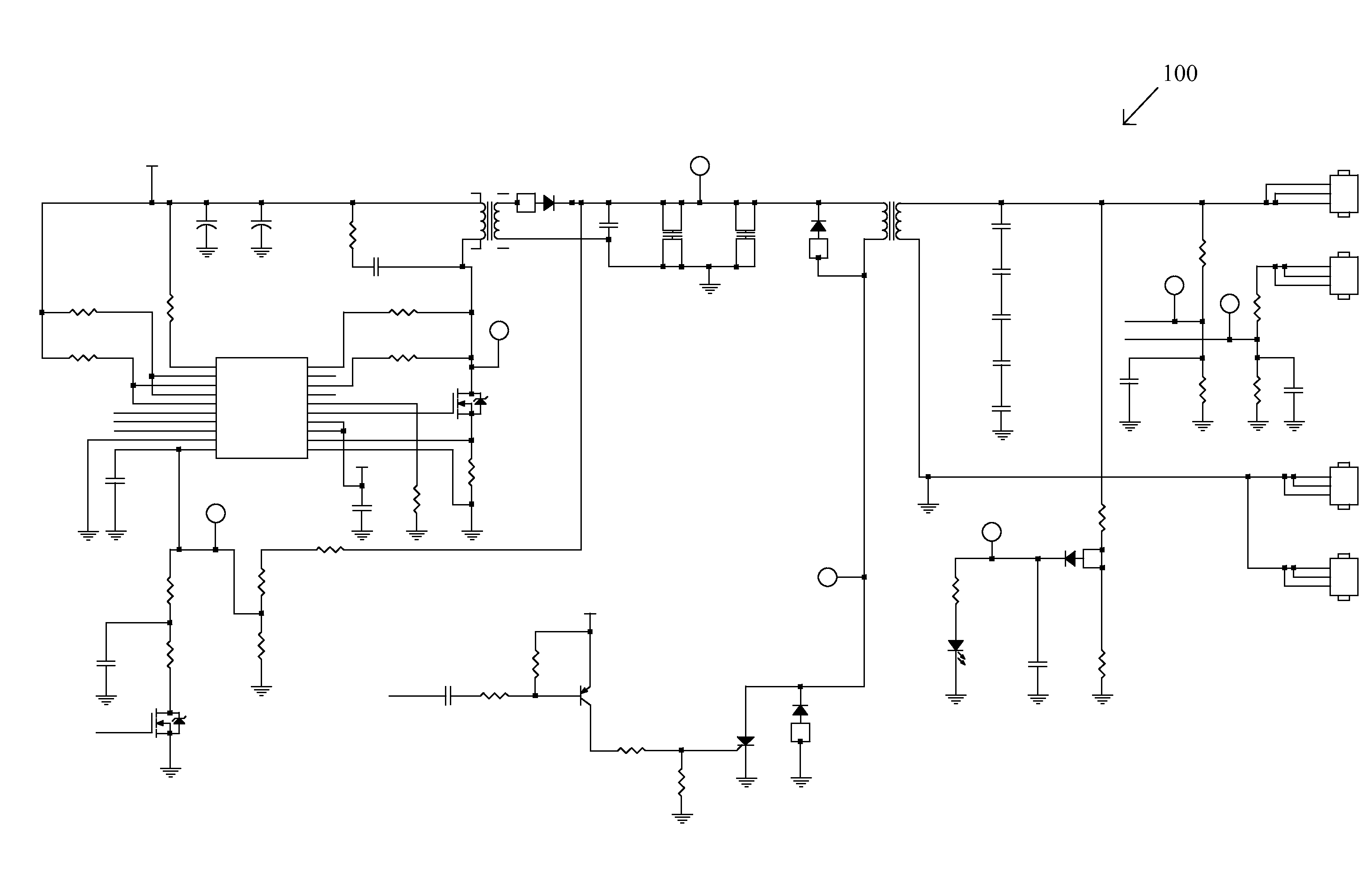
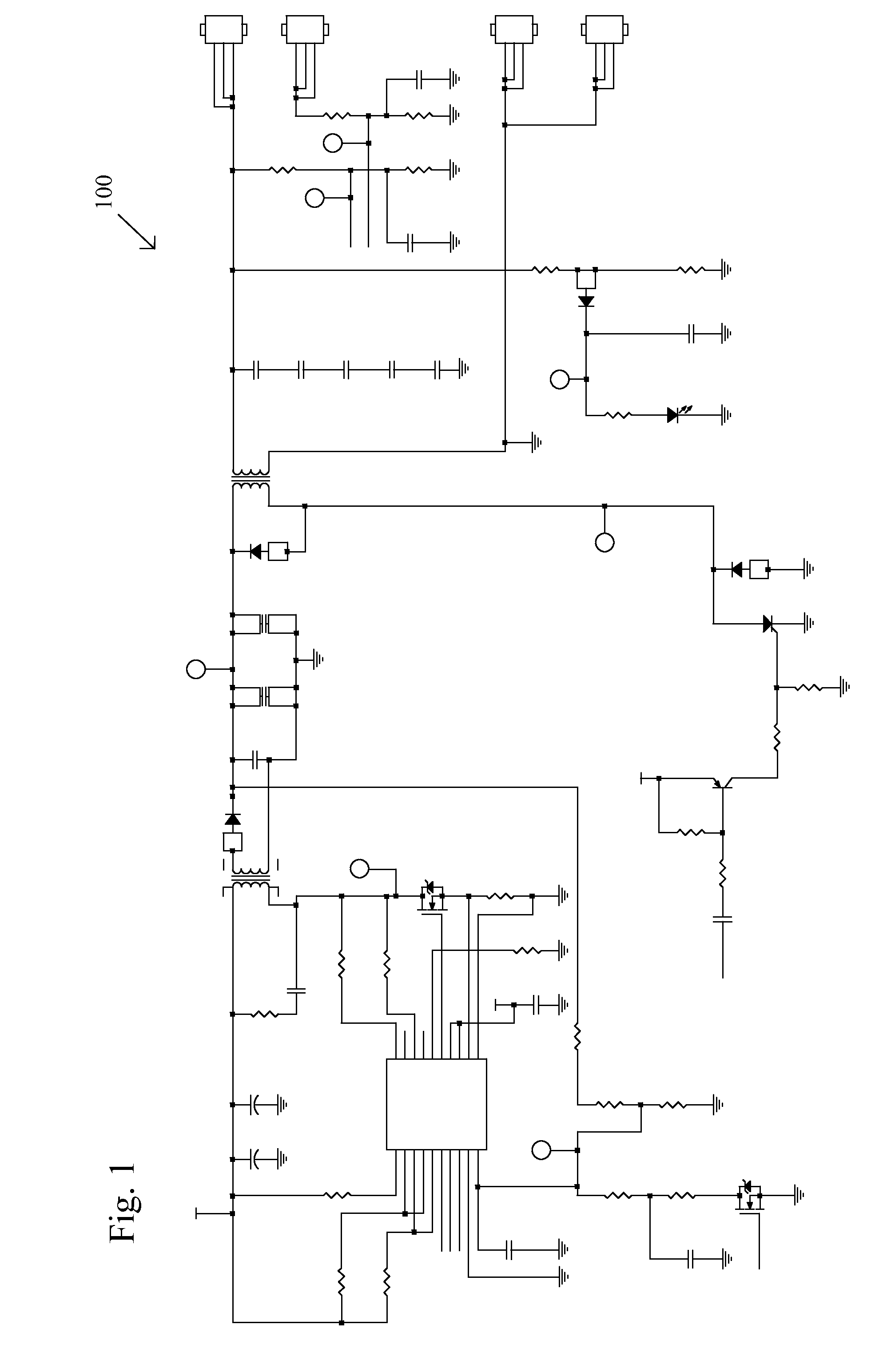
[0018]An electric fence may be used for security or animal control. An electric fence system preferably includes an electric fence, an energizer electrically coupled to the electric fence, forming a conduction route along the electric fence, and providing a continuously-variable power output of electricity to the electric fence, and a microprocessor operatively coupled to the energizer to produce the first continuously-variable power output, operatively coupled to sample the continuously-variable power output and a reflected return signal over time, and operatively coupled to sample a transmitted return signal over time. The microprocessor may be separate from the energizer or incorporated into the energizer.

[0019]An adjustable electric signal generator produces an initial signal. The system couples this signal to a single-wire transmission line. The signal propagates down the single-wire transmission line towards the opposite end. In a preferred embodiment, a receiver monitors the ...


PUM


Abstract

An electric fence control unit includes a signal generator, a first signal receiver, a second signal receiver, a signal processing and control unit, and a communications interface. The signal generator generates and transmits an adjustable power signal along a conduction path of the electric fence. The signal receivers sample signal outputs at a driven end and at an open end of the fence line. The signal processing and control unit receives and analyzes the first signal output and the second signal output. The communications interface transmits results from processing the first signal output and the second signal output to a service center. The power signal is adjustable to any capacity power level between a maximum power level and a minimum power level to match a load of the electric fence. Methods of monitoring the electric fence, including adjusting a power level of the adjustable power signal, are also disclosed.

Description

REFERENCE TO RELATED APPLICATIONS[0001]This application claims one or more inventions which were disclosed in Provisional Application No. 61 / 787,425, filed Mar. 15, 2013, entitled “SYSTEMS AND METHODS OF PROVIDING ENHANCED ELECTRIC FENCE DIAGNOSTICS”. The benefit under 35 USC §119(e) of the United States provisional application is hereby claimed, and the aforementioned application is hereby incorporated herein by reference.BACKGROUND OF THE INVENTION[0002]1. Field of the Invention[0003]The invention pertains to the field of electrical fences. More particularly, the invention pertains to systems and methods of enhanced electrical fence diagnostics.[0004]2. Description of Related Art[0005]Electric fence energizers provide an electrical pulse down a fence wire that is intended to deter intruders. This pulse is designed to be non-lethal but of sufficient magnitude to be an effective deterrent. Unfortunately, current conventional energizers have several drawbacks. These drawbacks include...

Claims


Application Information

Patent Timeline
Patent Type & Authority Applications(United States)
IPC IPC(8): H05C1/04G01R21/133G01R31/02G01R31/36
CPCH05C1/04G01R31/02G01R21/133G01R31/3606G01R31/11G01R31/2827H05C1/06G01R31/382
Inventor DEMAO, JACKBATTI, STEVEBAXTER, MICHAELROBERTS, MARK
Owner ELECTRIC GUARD DOG
Why Eureka
Try Eureka