Micro valve device and valve body assembly

a valve body and micro-ventilation technology, applied in the direction of multiple-way valves, valve arrangements, mechanical equipment, etc., can solve the problems of deviation and even failure of the standard reference pressure, and achieve the effect of accurate controllabl

Active Publication Date: 2016-02-04
ZHEJIANG DUNAN ARTIFICIAL ENVIRONMENT
View PDF8 Cites 5 Cited by
  • Summary
  • Abstract
  • Description
  • Claims
  • Application Information

AI Technical Summary

Benefits of technology

[0006]One objective of embodiments of the present disclosure is to provide an active micro valve device based on a MEMS technology, which can simultaneously output at least two types of fluids having different pressures or flow rates. The micro valve device can be used for controlling a pilot valve of a main valve, and the at least two types of fluids output by the pilot valve have a relative pressure difference, so that opening and closing or a flow proportion of the fluids passing through fluid channel of the main valve are accurately controllable, so as to achieve the purpose of controlling the flow rates.

Problems solved by technology

However, such a mechanism may cause phenomena such as aging and failure, so that deviation and even failure will occur to the standard reference pressure.

Method used


Image

  • Micro valve device and valve body assembly
  • Micro valve device and valve body assembly
  • Micro valve device and valve body assembly

Examples


embodiment 1

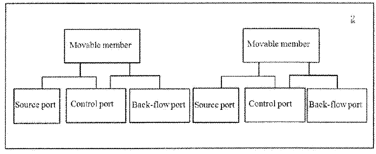
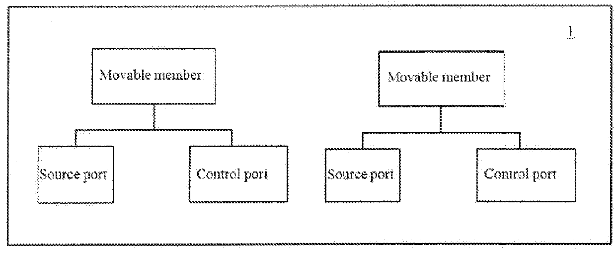
[0035]The embodiment of the present disclosure provides a micro valve device, the micro valve device comprising a main body. The main body defines a chamber therein, and the main body includes a source port and at least two control ports. The source port and the control port can be communicated with the chamber. In addition, the micro valve device further comprises at least two movable members, and the at least two movable members respectively control a conducting state or a blocking state between each of the above-described at least two control ports and the source port correspondingly. Each movable member may be located in two positions, i.e., a first position and a second position. Upon each movable member being located in the first position, a corresponding control port may be in fluid communication with the source port through at least a portion of the chamber; and upon each movable member being located in the second position, a fluid path between the corresponding control port...

embodiment 2

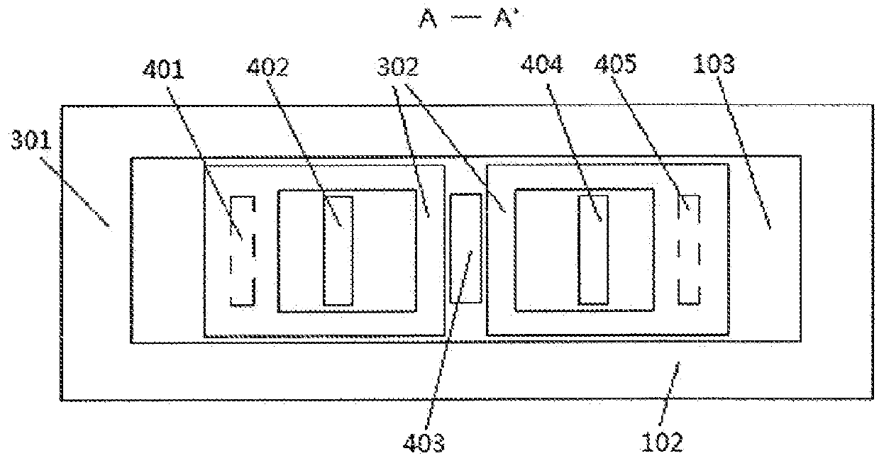
[0046]FIG. 3 illustrates a structure of a micro valve device according to the embodiment of the present disclosure, wherein (a) is a cross-sectional schematic diagram; while (b) is a plan schematic diagram. In addition, it should be noted that, this embodiment is another specific example according to the present disclosure, and the features described in the above-described Embodiment 1 are also applicable to this embodiment or may be appropriately combined with this embodiment. For simplicity of description, contents the same as those in the above-described Embodiment 1 will be appropriately simplified or omitted in this embodiment.

[0047]As illustrated in FIG. 3(a) and FIG. 3(b), the micro valve device comprises a cover layer 101, an intermediate layer 102 and a base layer 103. The cover layer 101, the intermediate layer 102 and the base layer 103 stacked sequentially form a main body of the micro valve device. The intermediate layer 102 may be of a frame-shaped structure, so as to ...

embodiment 3

[0065]An embodiment of the present disclosure further provides a valve body assembly comprising a micro valve device and a main valve. FIG. 3 is a schematic diagram of the valve body assembly according to one embodiment of the present disclosure. Hereinafter, a structure of the valve body assembly according to the embodiment of the present disclosure and a principle on which the micro valve device controls the main valve are described in conjunction with FIG. 3.

[0066]The micro valve device 10 in the valve body assembly according to this embodiment may be the micro valve device according to any one of the above-described embodiments, and structures of the micro valve device will not be repeated here. In addition, the main valve 20 of the valve body assembly is not specifically limited by the embodiment of the present disclosure either. For example, the main valve 20 may have a main body 201 of the main valve and a valve core 203, the main body 201 of the main valve has therein a main...


PUM


Abstract

Provided are a micro valve device and a valve body assembly. The micro valve device comprises at least two control ports (402, 404) and at least two movable members (302), wherein the at least two movable members (302) respectively control each of the at least two control ports (402, 404) to realize that opening and closing of the control ports (402, 404) are independently controlled, so that the at least two control ports (402, 404) can output fluids with the same or different flow rate(s) or pressure(s). The valve body assembly comprises the micro valve device.

Description

TECHNICAL FIELD[0001]The present disclosure relates to a micro electromechanical system (MEMS), and more particularly, to a micro valve device and a valve body assembly based on a MEMS technology.BACKGROUND[0002]A micro valve device belongs to a key device in microfluidic control, and has important applications in fields such as biology, medical care and refrigeration. The micro valve device based on a micro-electromechanical system (MEMS) technology has advantages such as accurate control, low cost, mass production, good stability and reliability, etc.[0003]In fluid control, the micro valve device may be used as a pilot valve for controlling a main valve, to achieve accurate control of an opening degree of the main valve, so as to reach a purpose of controlling fluid flow.[0004]Chinese Patent Application No. 200580011090.3 and No. 200780046457.4, and U.S. Pat. Nos. 6,523,560, 7,011,378 and 6,761,420 disclose a micro valve device which can be used as a pilot valve, wherein only one ...

Claims


Application Information

Patent Timeline
Patent Type & Authority Applications(United States)
IPC IPC(8): F16K99/00
CPCF16K99/0011F16K99/0028F16K99/0048F16K99/0059
Inventor ZHANG, SHENGCHANG
Owner ZHEJIANG DUNAN ARTIFICIAL ENVIRONMENT
Why Eureka
Try Eureka