Vehicle radar system with blind spot detection

a radar system and blind spot technology, applied in the field of vehicle radar systems, can solve the problems of multiple analog receiver circuits, relatively high cost, and approaches to digital beam forming, and achieve the effect of facilitating the classification of guardrails

Active Publication Date: 2016-02-04
VEONEER US LLC
View PDF3 Cites 20 Cited by
  • Summary
  • Abstract
  • Description
  • Claims
  • Application Information

AI Technical Summary

Benefits of technology

[0008]As a result of this feature of the Tx pattern, the return from a stationary object, e.g., wall or guardrail, having zero range rate, i.e., no Doppler, is minimized, while the return from the guardrail in the forward and rearward directions has a measurable Dop

Problems solved by technology

This approach has the disadvantage of requiring multiple analog receiver circuits, which can be relativel

Method used


Image

  • Vehicle radar system with blind spot detection
  • Vehicle radar system with blind spot detection
  • Vehicle radar system with blind spot detection

Examples


Embodiment Construction

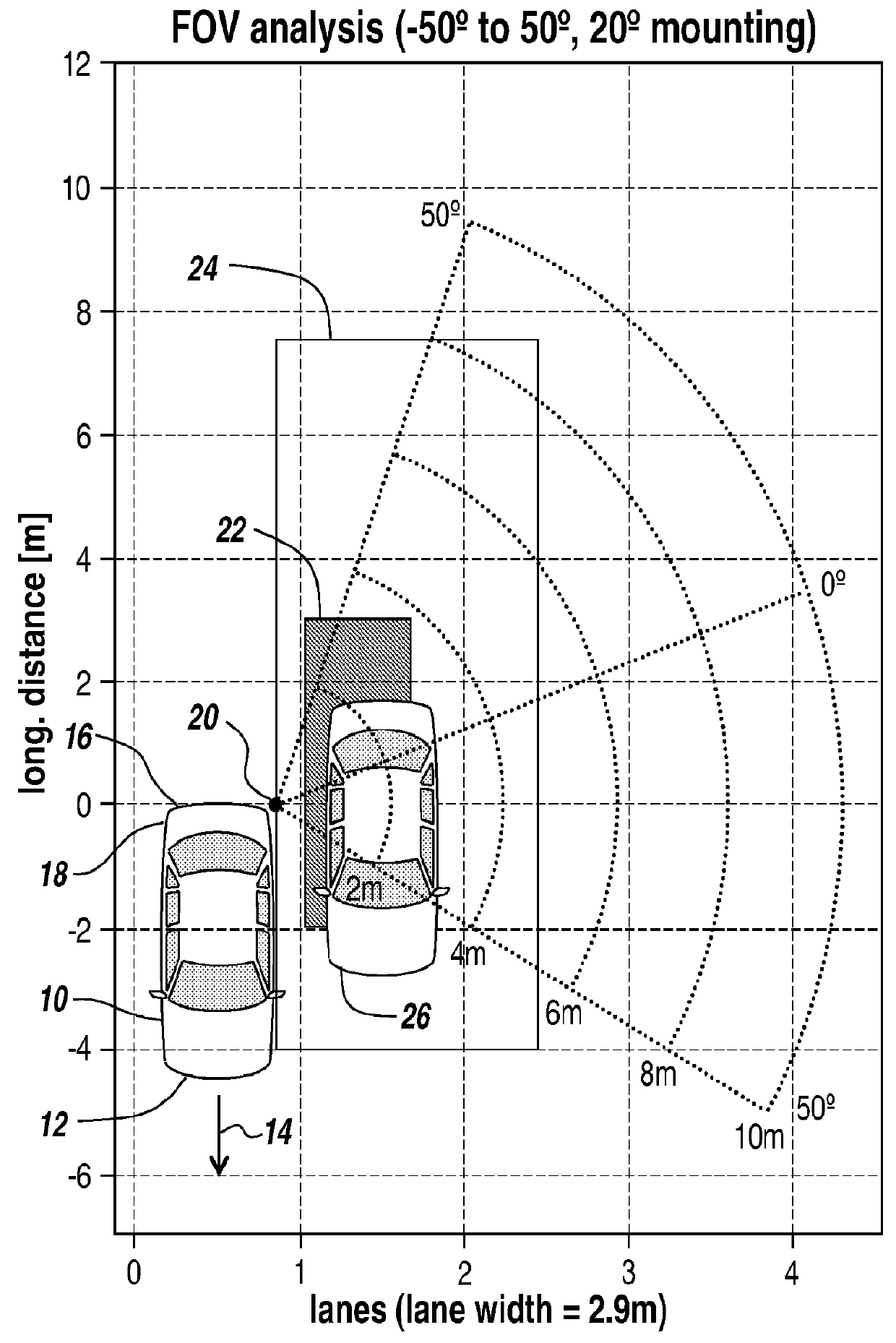
[0037]FIG. 1 includes a schematic diagram which illustrates a vehicle 10 equipped with a radar system for blind spot detection / monitoring, according to some exemplary embodiments. In FIG. 1, vehicle 10 is illustrated such that the front end 12 of vehicle 10 is facing in the direction indicated by directional arrow 14, which indicates the direction of travel of vehicle 10. The rear end 18 of vehicle 10 includes a rear bumper 16 to which the radar transceiver 20 according to exemplary embodiments is attached. It should be noted that radar transceiver 20 is also interchangeably referred to herein as a “radar sensor” or simply as a “sensor.” In some particular embodiments, in accordance with Blind Spot Information System (BSIS) and Rear Cross Traffic Alert system requirements, radar sensor 20 provides a minimum total 100-degree field of view, including a minimum +50 degree field of view to provide timely detection of a vehicle approaching from the rear and a minimum −50 degree field of ...


PUM


Abstract

A vehicle radar system for monitoring a blind spot of a vehicle includes a radar transmitter mounted on the vehicle and a transmitting antenna coupled to the radar transmitter. The transmitting antenna transmits radiation in a pattern into a region adjacent to the vehicle, the pattern comprising a first radiation lobe and a second radiation lobe. A null region of the pattern between the first lobe and the second lobe is directed into the region approximately perpendicular to a longitudinal axis of the vehicle, the longitudinal axis running between a rear end of the vehicle and a front end of the vehicle and running along a line of travel of the vehicle.

Description

BACKGROUND[0001]1. Technical Field[0002]This application is related to vehicle radar systems, and, more particularly, to vehicle radar systems with blind spot detection.[0003]2. Discussion of Related Art[0004]Some automotive radar systems monitor the immediate surroundings of a host vehicle and can enable safety or comfort features such as blind spot detection and lateral collision avoidance. Blind spot detection radar sensors must cover a very wide area and must have the ability to classify the obstacles in the radar field of view. In particular, for example, the radar sensor must be able to distinguish a flat wall or guardrail from a stagnant vehicle at low speed, i.e., a vehicle travelling in the same direction and at approximately the same speed as the host vehicle.[0005]Conventional vehicle blind spot detection / monitoring systems typically implement one broad radar transmit pattern and an array of receivers. The receiver beam is either steered or formed digitally. For example, ...

Claims


Application Information

Patent Timeline
IPC IPC(8): G01S13/931G01S7/28
CPCG01S13/931G01S2013/9332G01S7/2813G01S2013/9315
Inventor DE MERSSEMAN, BERNARDERIKSSON, OLOFANDERSSON, ROIN
Owner VEONEER US LLC
Why Eureka
Try Eureka