Charged particle acceleration device

a technology of acceleration device and charge, which is applied in the direction of nuclear engineering, greenhouse gas reduction, nuclear reactors, etc., can solve the problems of limited x-ray flux and fundamental limitation of the maximum energy of x-rays that the mechanoluminescent x-ray generator can obtain

Active Publication Date: 2016-02-04
RGT UNIV OF CALIFORNIA
View PDF3 Cites 10 Cited by
  • Summary
  • Abstract
  • Description
  • Claims
  • Application Information

AI Technical Summary

Problems solved by technology

Mechanoluminescent x-ray generators appear to have a fundamental limitation regarding the maximum energy of x-rays they can obtain (˜50 kV).
Furthermore, the x-ray flux is limited v

Method used


Image

  • Charged particle acceleration device
  • Charged particle acceleration device
  • Charged particle acceleration device

Examples


Embodiment Construction

[0015]Some embodiments of the current invention are discussed in detail below. In describing embodiments, specific terminology is employed for the sake of clarity. However, the invention is not intended to be limited to the specific terminology so selected. A person skilled in the relevant art will recognize that other equivalent components can be employed and other methods developed without departing from the broad concepts of the current invention. All references cited anywhere in this specification, including the Background and Detailed Description sections, are incorporated by reference as if each had been individually incorporated.

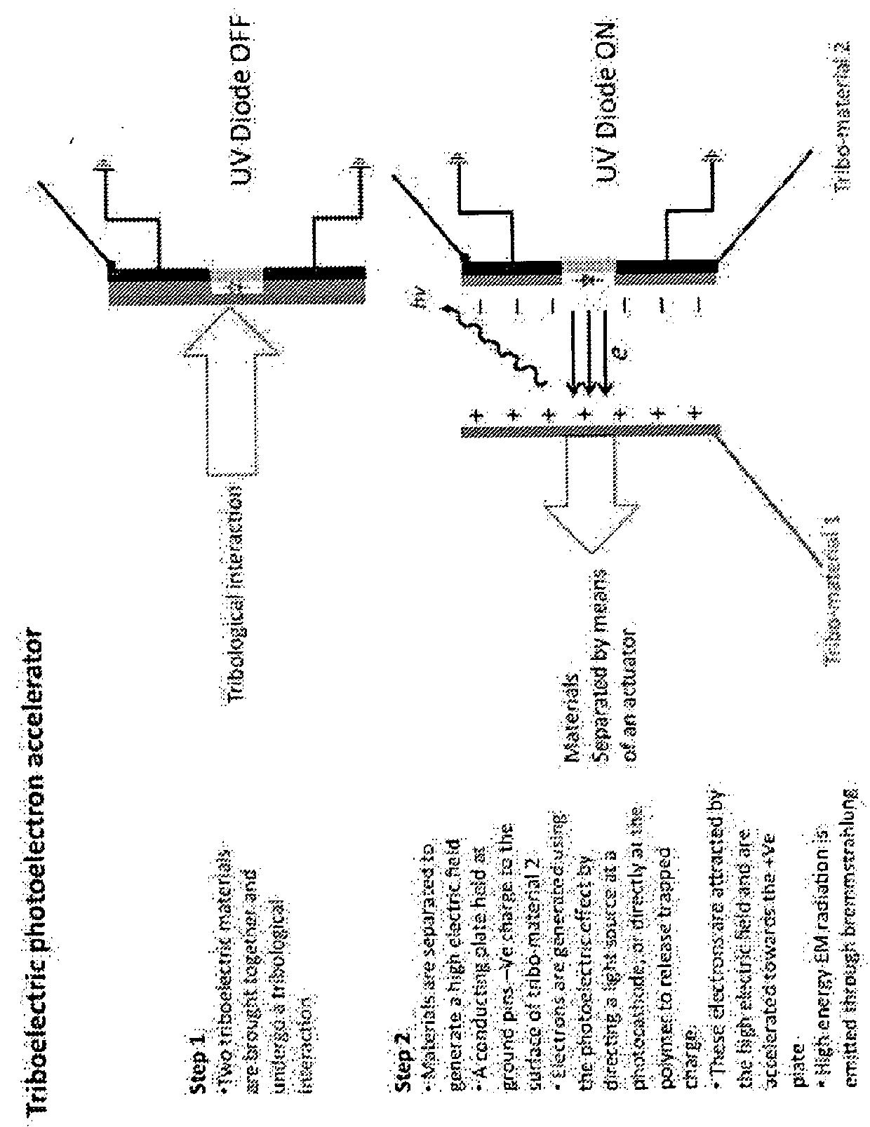
[0016]As noted in the previous section, mechanoluminescent x-ray generators appear to have a fundamental limitation regarding the maximum energy of x-rays they can obtain (˜50 kV). Furthermore, the x-ray flux is limited via a poorly understood process whereby the polymer that acts as the ‘electron gun’ (in the x-ray tube sense) restricts the electron ...


PUM


Abstract

A charged particle acceleration device according to some embodiments of the current invention includes a first triboelectric element, a second tribo-electric element arranged proximate the first tribo-electric element to be brought into contact with and separated from the first triboelectric element, an actuator assembly operatively connected to at least one of the first and second triboelectric elements to bring the first and second triboelectric elements into contact with each other and to separate the first and second triboelectric elements from each other, and a charged-particle source configured to provide charged particles in a gap between the first and second triboelectric elements.

Description

CROSS-REFERENCE OF RELATED APPLICATION[0001]This application claims priority to U.S. Provisional Application No. 61 / 603,145 filed Feb. 24, 2012, the entire contents of which are hereby incorporated by reference.UNITED STATES FEDERAL GOVERNMENT SUPPORT[0002]This invention was made with Government support under Grant No. W81XWH-10-1-1049 awarded by the USAMRMC—TATRC, the U.S. Department of Defense. The U.S. Government has certain rights in this invention.BACKGROUND[0003]1. Field of Invention[0004]The field of the currently claimed embodiments of this invention relates to charged particle acceleration devices, and more particularly to triboelectric charged particle acceleration devices.[0005]2. Discussion of Related Art[0006]Triboelectricity has been utilized in fundamental scientific research as a source of high electrostatic potential for over three centuries, from the early electrostatic apparatus of Haukesbee (F. Haukesbee, Physico-Mechanical experiments on various subjects (London...

Claims


Application Information

Patent Timeline
IPC IPC(8): G21G1/02G21B1/11H05H15/00
CPCG21G1/02G21B1/11H05H15/00Y02E30/10
Inventor PUTTERMAN, SETH J.HIRD, JONATHANNARANJO, BRIAN
Owner RGT UNIV OF CALIFORNIA
Why Eureka
Try Eureka