Puncture Needle for Photoacoustic Imager and Photoacoustic Imager

Inactive Publication Date: 2016-02-11
PREXION
View PDF0 Cites 5 Cited by
  • Summary
  • Abstract
  • Description
  • Claims
  • Application Information

AI Technical Summary

Benefits of technology

[0007]The present invention has been proposed in order to solve the aforementioned problem, and an object of the present invention is to provide a puncture needle for a photoacoustic imager capable of more efficiently generating an acoustic wave so that the pos

Problems solved by technology

When a light source employing a semiconductor light-emitting element such as an LED element is employed, therefore, it is disadvantageously impossible

Method used


Image

  • Puncture Needle for Photoacoustic Imager and Photoacoustic Imager
  • Puncture Needle for Photoacoustic Imager and Photoacoustic Imager
  • Puncture Needle for Photoacoustic Imager and Photoacoustic Imager

Examples


first embodiment

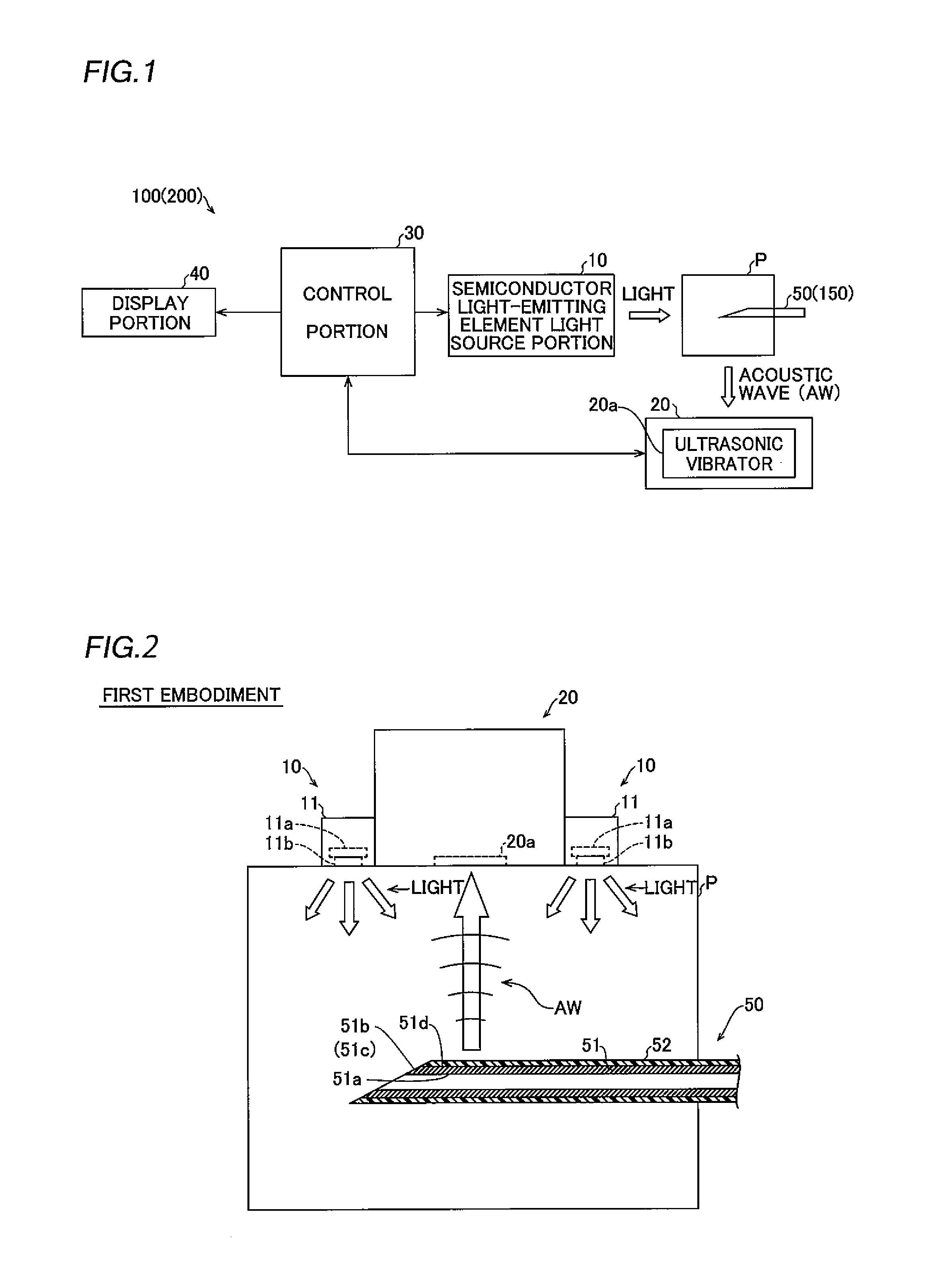
[0037]First, the structure of a photoacoustic imager 100 according to a first embodiment of the present invention is described with reference to FIGS. 1 to 4.

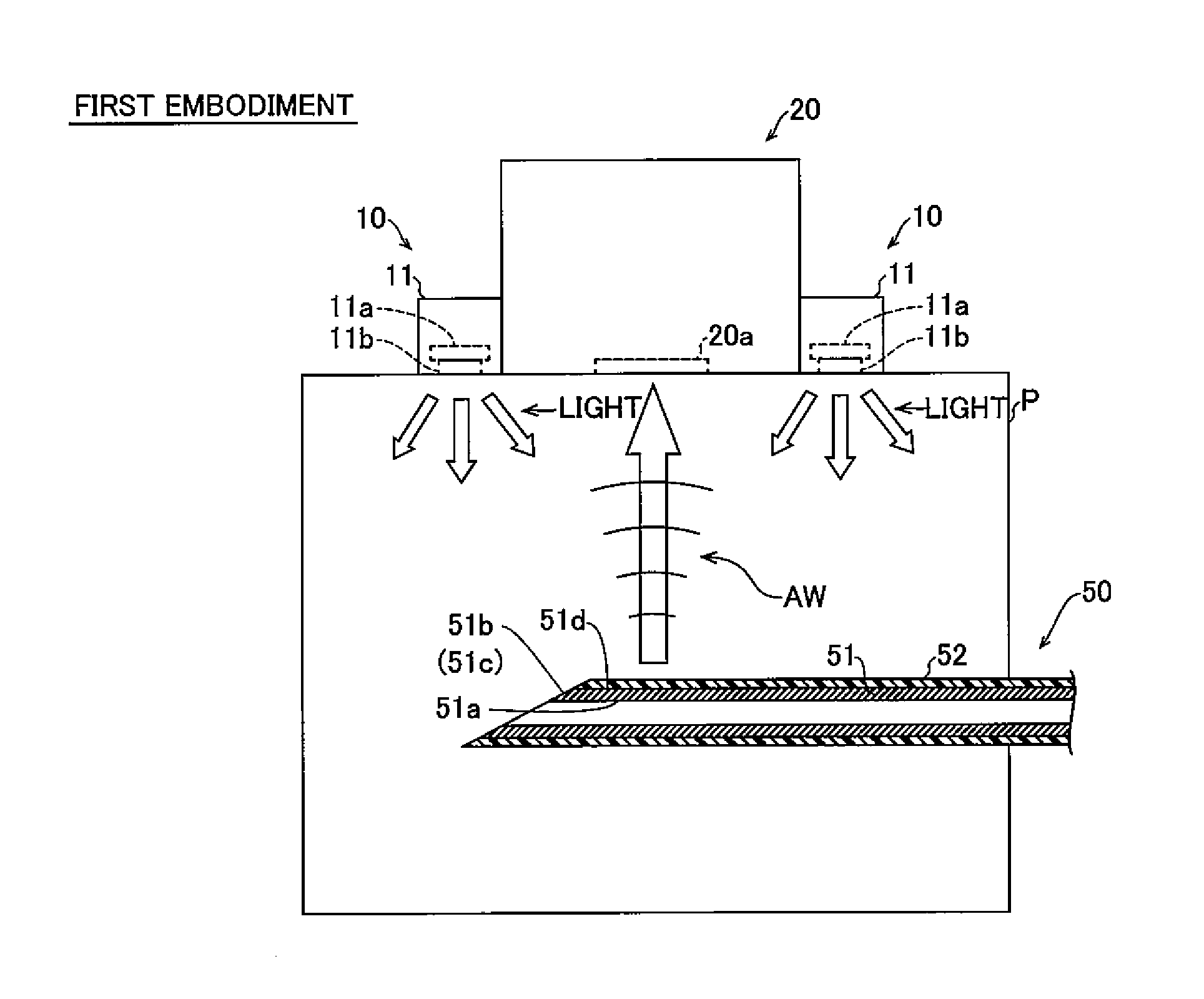
[0038]The photoacoustic imager 100 according to the first embodiment of the present invention includes a semiconductor light-emitting element light source portion 10, a detection portion 20, a control portion 30, a display portion 40 and a puncture needle 50, as shown in FIG. 1. The puncture needle 50 is an example of the “puncture needle for a photoacoustic imager” in the present invention.

[0039]As shown in FIGS. 1 and 2, the semiconductor light-emitting element light source portion 10 includes two semiconductor light-emitting element light sources 11, and is configured to apply pulsed light for measurement to a specimen P from each of the two semiconductor light-emitting element light sources 11. The two semiconductor light-emitting element light sources 11 are arranged in the vicinity of the detection portion 20 on different...

second embodiment

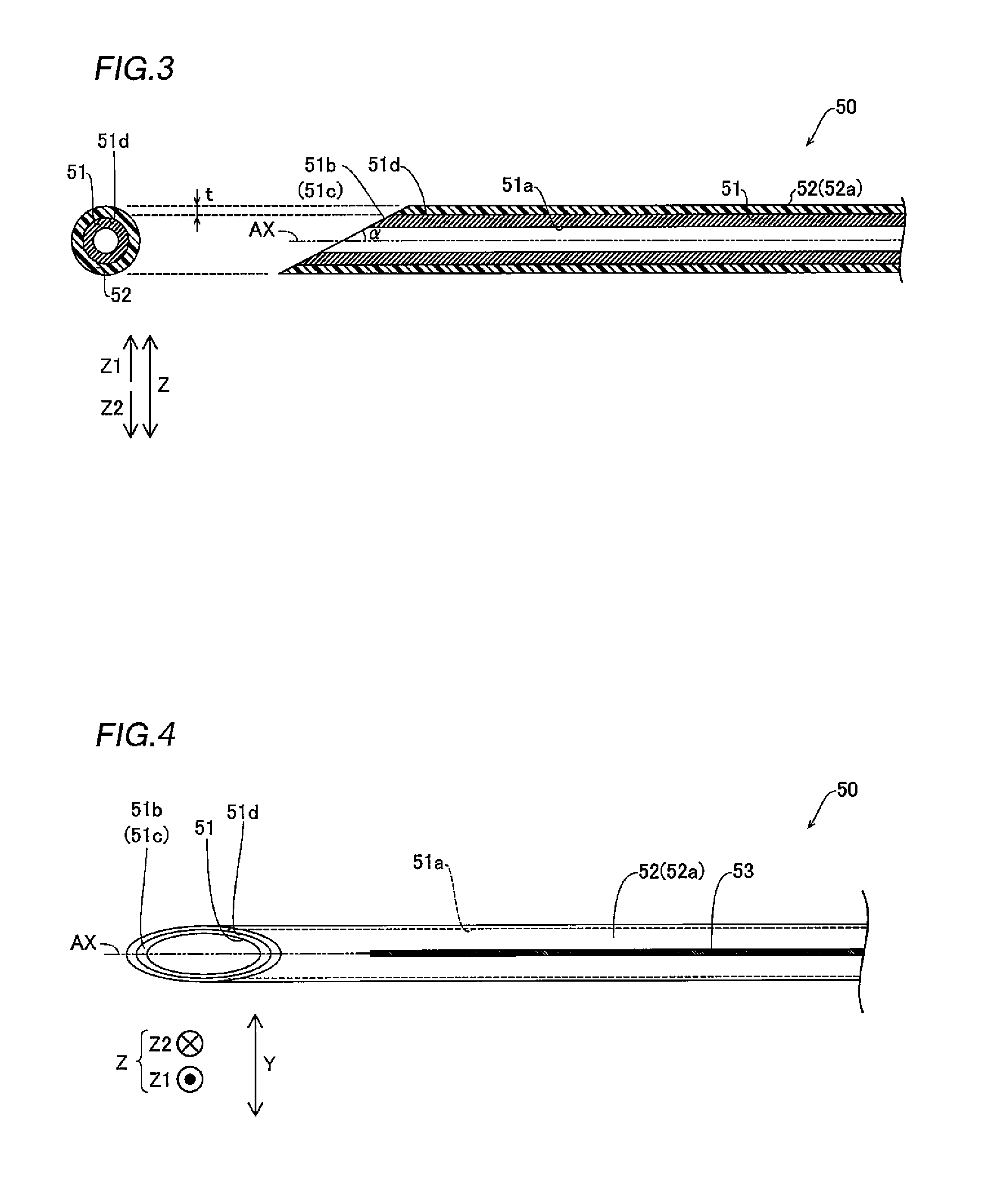
[0080]A photoacoustic imager 200 according to a second embodiment of the present invention is now described with reference to FIGS. 1 and 5. According to the second embodiment, the photoacoustic imager 200 is provided with a plurality of (five) marking portions 153 in the form of graduations, dissimilarly to the structure of the photoacoustic imager 100 according to the aforementioned first embodiment having the marking portion 53 provided in the form of a line directed toward the extensional direction of the needle tube 51a. Structures identical to those of the aforementioned first embodiment are denoted by the same reference signs, and redundant description is omitted.

[0081]The photoacoustic imager 200 according to the second embodiment of the present invention includes a puncture needle 150, as shown in FIG. 1. The puncture needle 150 is substantially identical in structure to the puncture needle 50 according to the aforementioned first embodiment, except that the marking portion...


PUM


Abstract

This puncture needle for a photoacoustic imager is a puncture needle for a photoacoustic imager including a semiconductor light-emitting element light source portion, and includes a puncture needle body and a cover layer, formed on a surface of the puncture needle body, made of a cover material containing a material higher in light absorptivity than the puncture needle body and a resin material larger in linear expansion coefficient than the puncture needle body.

Description

BACKGROUND OF THE INVENTION[0001]1. Field of the Invention[0002]The present invention relates to a puncture needle for a photoacoustic imager and a photoacoustic imager.[0003]2. Description of the Background Art[0004]A photoacoustic imager including a puncture needle body is known in general, as disclosed in Japanese Patent Laying-Open No. 2013-27513.[0005]Japanese Patent Laying-Open No. 2013-27513 discloses a photoacoustic imager including a laser beam source and a puncture needle body. This photoacoustic imager is configured to detect an acoustic wave signal (an acoustic wave) generated by the puncture needle body by applying a laser beam thereto from the laser beam source, so that the position of the puncture needle body in a specimen can be confirmed on a photoacoustic image based on the acoustic wave signal. In this photoacoustic imager, portions coated with a light scattering material and a light absorbing material respectively are provided on a surface of the puncture needle ...

Claims


Application Information

Patent Timeline
IPC IPC(8): A61B5/00A61B17/34
CPCA61B5/0095A61B2019/5483A61B17/3403A61B5/061A61B5/685A61B2090/3983
Inventor NAKATSUKA, HITOSHI
Owner PREXION
Why Eureka
Try Eureka