Microwave plasma generating device

Inactive Publication Date: 2006-03-30
HAMAMATSU FOUNDATION FOR SCIENCE & TECHNOLOGY PR
View PDF6 Cites 12 Cited by
  • Summary
  • Abstract
  • Description
  • Claims
  • Application Information

AI Technical Summary

Benefits of technology

[0013] The microwave excitation plasma can be efficiently generated without using an ECR system. The microwave is directly supplied into the vessel from the electrode of the launcher without passing

Problems solved by technology

Therefore, an entire device tends to become large, and there is a problem in that a large plasma space cannot be ensured.
Furthermore, an industrial desire to generate a high density plasma in a large space is not satisfied since the operation pressure (gas partial pressure) must be regulated at a relatively low pressure (a high degree of vacuum).
However, in

Method used


Image

  • Microwave plasma generating device
  • Microwave plasma generating device
  • Microwave plasma generating device

Examples


Embodiment Construction

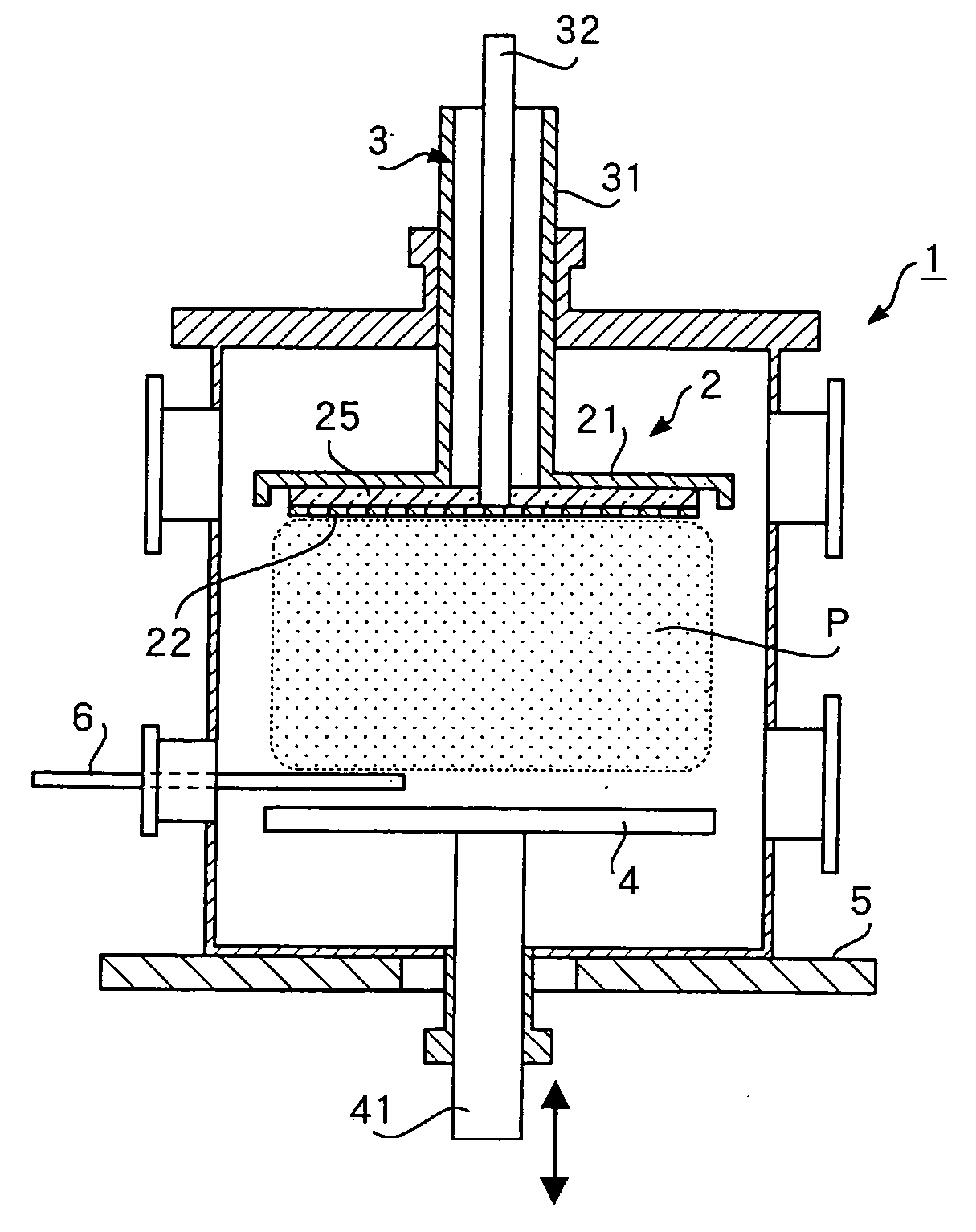
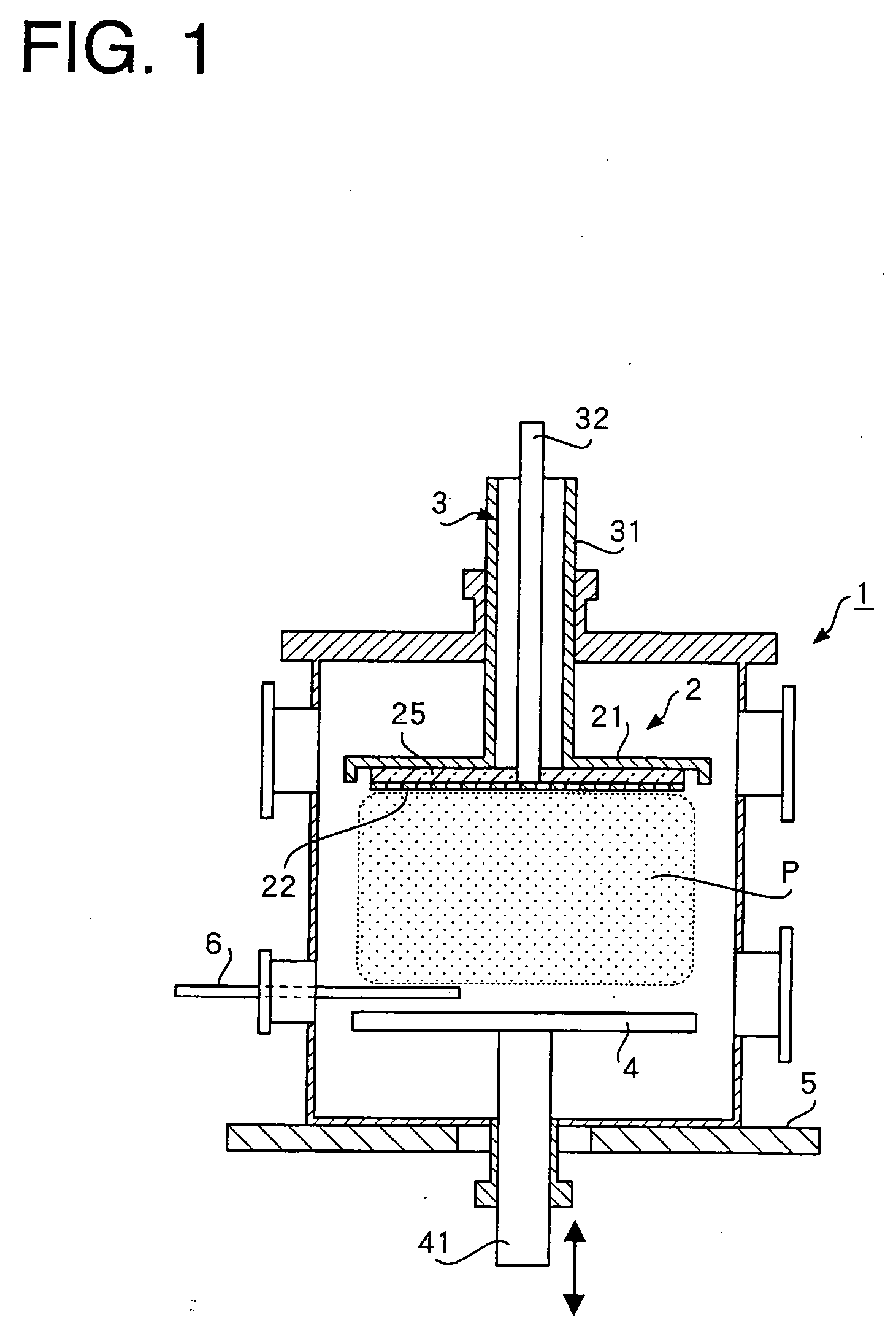
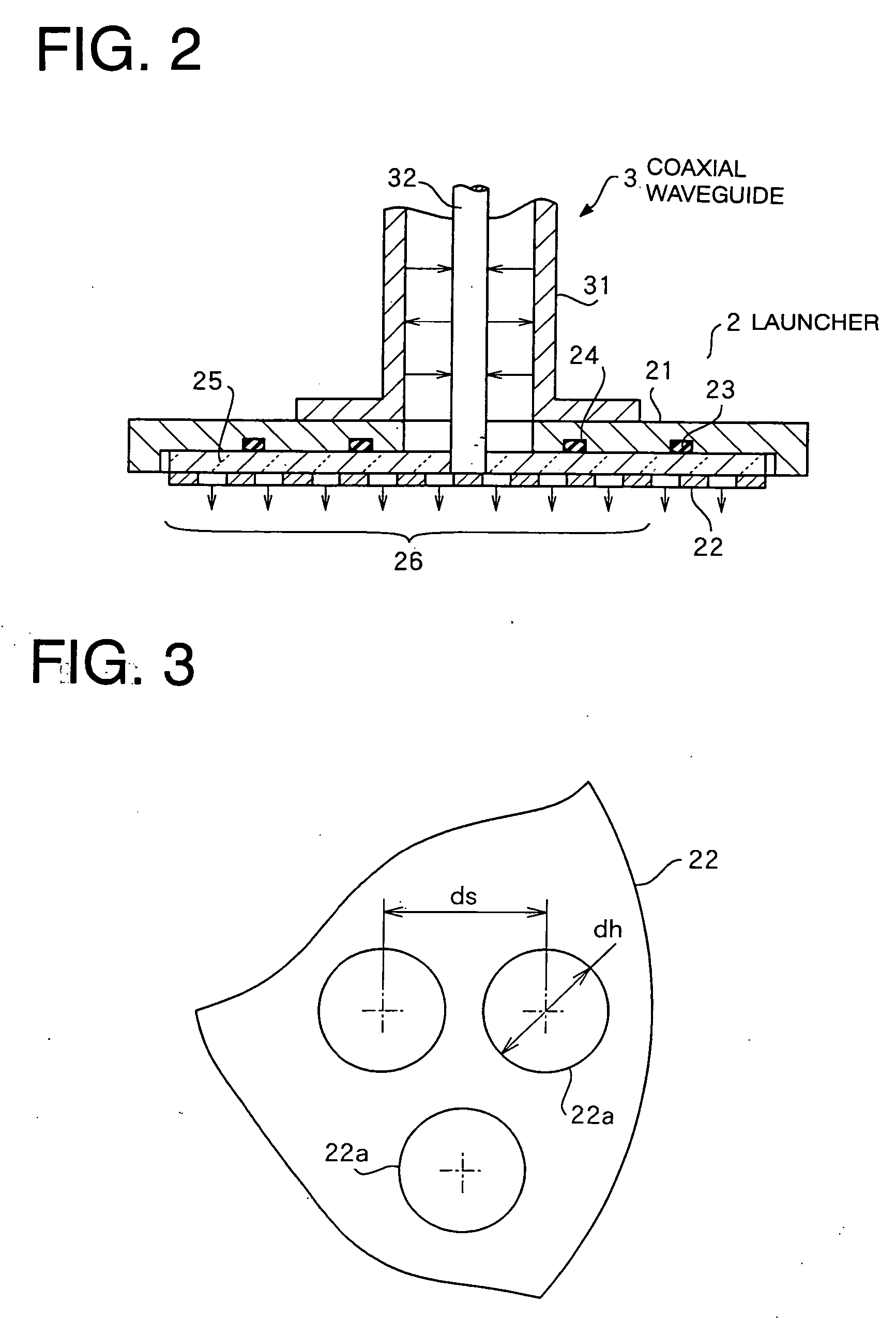
[0018] A device according to an embodiment of the present invention will be described below with reference to the drawings. FIG. 1 is a sectional view of a key portion of a microwave plasma generator according to the embodiment of the present invention. FIG. 2 is a magnified sectional view of a launcher portion in the above-described embodiment. FIG. 3 is a magnified diagram of a part of a second conductor plate of the above-described launcher. FIG. 4 is a plan view of the above-described device and a block diagram of a driving source.

[0019] The plane configuration of the device in the present embodiment and a driving circuit are shown in FIG. 4. A 2.45-GHz microwave oscillator (magnetron) is used as a microwave source 9 to generate an excitation microwave. This microwave source 9 is driven by a microwave source driving device 15. The control signal (containing the negative feedback signal) 15a is transmitted to the microwave source driving device 15 such that the magnetron can be ...


PUM

PropertyMeasurementUnit
Diameteraaaaaaaaaa
Distanceaaaaaaaaaa
Perimeteraaaaaaaaaa

Abstract

A microwave plasma generator is provided in which a gas in a vacuum vessel is directly excited by an evanescent wave from a microwave resonator disposed in the vessel without using an ECR system. The microwave plasma generator of the present invention includes a microwave source to generate an excitation microwave, a discharge gas source, a plasma generation vacuum vessel to be supplied with a gas from the discharge gas source, a coaxial waveguide to introduce the excitation microwave into the vessel, and a parallel plate launcher disposed in the vessel. In the parallel plate launcher, a resonant cavity is constructed from a first conductor plate connected to an outer conductor of the coaxial waveguide, a dielectric plate, and a second conductor plate connected to a central conductor of the coaxial waveguide and provided with a plurality of openings to emit evanescent microwaves into the vacuum vessel.

Description

BACKGROUND OF THE INVENTION [0001] 1. Field of the Invention [0002] The present invention relates to a plasma generator in which a carrier gas in a vacuum chamber is excited by only a microwave so as to generate plasma. [0003] 2. Description of the Related Art [0004] An electron cyclotron resonance (ECR) plasma device is known. Since a magnetic field is used for this type of plasma device, a magnetic field generator is required. Therefore, an entire device tends to become large, and there is a problem in that a large plasma space cannot be ensured. Furthermore, an industrial desire to generate a high density plasma in a large space is not satisfied since the operation pressure (gas partial pressure) must be regulated at a relatively low pressure (a high degree of vacuum). [0005] With respect to the above-described electron cyclotron resonance (ECR) plasma device and the like, a plasma generator in which a vacuum vessel to be supplied with a carrier gas is excited through a quartz wi...

Claims


Application Information

Patent Timeline
IPC IPC(8): C23C16/00H01L21/306C23C16/511H05H1/46H01J37/32H01L21/3065H01L21/31
CPCH01J37/32247H01J37/32192
Inventor NAGATSU, MASAAKI
Owner HAMAMATSU FOUNDATION FOR SCIENCE & TECHNOLOGY PR
Why Eureka
Try Eureka