Oil Filter Element and Oil Filter

a technology of oil filter and oil filter housing, which is applied in the direction of cartridge filter, filtration separation, separation process, etc., can solve the problems of high manufacturing cost, achieve high user-friendly, particularly inexpensive manufacturing, and prevent contamination of the clean side of the oil filter housing with unfiltered oil on the crude side

Active Publication Date: 2016-02-11
MANN HUMMEL GMBH
View PDF3 Cites 8 Cited by
  • Summary
  • Abstract
  • Description
  • Claims
  • Application Information

AI Technical Summary

Benefits of technology

[0013]The oil filter can be manufactured particularly inexpensively and highly user-friendly.
[0014]Due to the fact that the oil filter element arranged in the oil filter housing fulfills the sealing function of the crude side of the oil filter with respect to the drain channel and/or the drain opening, as well as the central channel of the oil filter element, which is arranged on the clean side, the oil, which is on the crude side or the clean side of the oil filter, can be drained out of the oil filter in a controlled manner before replacing the oil filter element when the oil filter element is removed from the container part of the filter housing. The oil filter element may advantageously be releasably attached to the housing co

Problems solved by technology

In the prior art, the employed radial and axial sealing elements are designed in one piece with one another, i.e., formed by

Method used


Image

  • Oil Filter Element and Oil Filter
  • Oil Filter Element and Oil Filter
  • Oil Filter Element and Oil Filter

Examples


Embodiment Construction

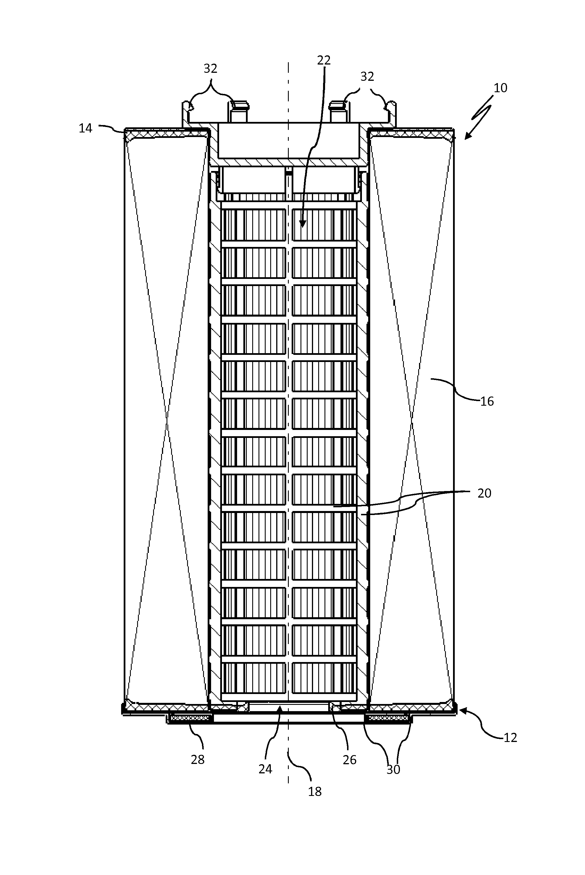
[0021]FIG. 1 shows an oil filter element 10 in a longitudinal section view. The oil filter element 10 has a first end disk 12 and a second end disk 14 as well as a filter medium 16 of an annular arrangement, held between the two end disks 12, 14. The oil to be filtered flows through the filter medium 16 from the outside to the inside in a direction that is radial to the longitudinal axis 18 of the oil filter element 10.

[0022]The filter medium 16 is supported on the inside by a central tube 20. The central tube 20 is designed like a mesh and, as shown in FIG. 1, can be locked with the second end disk 14 or otherwise attached to the second end disk 14 and / or integrally molded on the second end disk 14. The central tube 20 delimits on the inside a central channel 22 into which the oil flows as it passes through the filter medium 16, i.e., is filtered. The central channel 22 extends between the two end disks 12, 14 in a direction that is axial to the longitudinal axis 18 of the oil filt...


PUM

PropertyMeasurementUnit
Adhesivityaaaaaaaaaa
Circumferenceaaaaaaaaaa
Elasticityaaaaaaaaaa

Abstract

An oil filter element has first and second end disks between which an annular filter medium is held. The oil to be filtered flows through the filter medium in a direction radial to the longitudinal axis of the oil filter element. The oil filter element has a central channel arranged on the clean side and provided with a central outlet opening in the region of the first end disk. A radial sealing element, formed by an elastically deformable inside circumferential section of the first end disk, is arranged in the region of the outlet opening. In addition, an axial sealing element is arranged on the outside of the first end disk. This axial sealing element is held on the first end disk by retaining elements. An oil filter having such an oil filter element is provided.

Description

BACKGROUND OF THE INVENTION[0001]The invention relates to an oil filter and an oil filter element comprising a first end disk and a second end disk and an annularly arranged filter medium that is secured between the two end disks so that the oil to be filtered can flow through it in a direction radial to the longitudinal axis of the oil filter element. The oil filter element has a central channel, which is downstream fluidically from the filter medium, i.e., is arranged on the clean side of the oil filter element. The central channel has a central outlet opening for the filtered oil at one end in the region of the first end disk. An elastically deformable radial sealing element is arranged in the region of the outlet opening, and an annular axial sealing element is arranged on the outside of the first end disk.[0002]Such oil filter elements are known from EP 1 254 692 B, for example, and are used in oil filters in which the filter housing comprises a container part that can be close...

Claims


Application Information

Patent Timeline
IPC IPC(8): B01D35/00B01D29/15
CPCB01D29/15B01D35/005B01D35/153B01D35/16B01D2201/291B01D2201/342B01D2201/4084
Inventor JOKSCHAS, GUENTERFAISST, MARCO
Owner MANN HUMMEL GMBH
Why Eureka
Try Eureka